4. Variations
While a full coordinate transformation includes rotation, scaling, and translation, there are situations where only one or two of the elements are necessary.
a. Rotation only
A rotation-only transformation is used to convert directions from one meridian reference to another. An example is converting magnetic to true directions.
Traverse line directions in Figure J-16 are referenced to Magnetic North.
|
|
|
Figure J-16 |
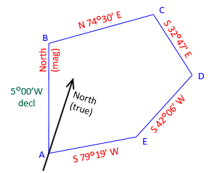
To obtain True bearings, each bearing must change numerically by 5°00' to the West to compensate for the declination. Figure J-17 Shows Magnetic and True meridians at each point.
|
|
|
Figure J-17 |
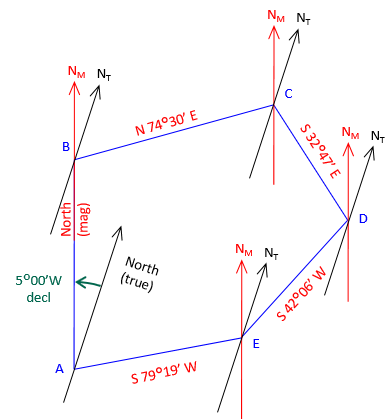
The True bearing of line AB is N 5°00' W; line BC is N69°30'E; line CD is S 37°47'E; ...
b. Translation only
When dealing with regional coordinate systems, the corners of a small survey may have large coordinates, Figure J-18. To work with smaller coordinates, the surveyor may subtract a one constant from all the North coordinates and another constant from the East coordinates.
|
|
|
Figure J-18 |
For traverse in Figure J-18, we could subtract 384,000.00 from the North coordinates and 2,307,000.00 from the East coordinates. The result would be Figure J-19.
|
|
|
Figure J-19 |
This effectively creates a local origin shown in Figure J-20 with trranslation parameters.
|
|
|
Figure J-20 |
Coordinate differences are still the same since each coordinate pair has been changed the same amount. Inverse and area computations are similarly unaffected outside the fact that the magnitude of the computations are somewhat simplified.
c. Translation and rotation
A typical field situation could be collecting data referenced to a base line without first knowing the base line's location. The data is relative to the base line so later fixing the base line fixes the data.
A field crew sets up on one control station and uses another as a backsight for a topo survey. Not knowing coordinates of either point they assume the coordinates of A, their total station instrument (TSI) location, and direction of the backsight line. From there they collect and reduce their topo data.
Later they are able to obtain point A's coordinates and the correct direction to point B. Figure J-21 shows what happened when they incorporate the control with their field data .
|
|
|
Figure J-21 |
Using this information, they are able to translate and rotate the topo data to its correct location, Figure J-22.
|
|
|
Figure J-22 |