3. Existing LDPs
a. Michigan NAD 27
Michigan had two sets of SPC systems developed on NAD 27:
- A three-zone transverse Mercator cylindric system conventionally fit to the Clarke 1866 ellipsoid
- A three-zone Lambert conic system fit to a elevation 800 feet above sea level
Reason for the latter is described in C&GS Publication 65-3 Plane Projection Tables - Michigan:
To eliminate necessity for "reduction to sea level” in the great majority of surveys in the State of Michigan, advantage has been taken of the fact that Michigan is, through out most of its area, quite flat, though at an appreciable elevation above sea level. It has been determined that, except for the extreme northwestern part of the Upper Peninsula, the general Elevation of the land seldom departs much more than about 200 feet from a mean value of 800 feet above sea level. Accordingly, the coordinate system has been computed on a reference surface that is approximately 800 feet above the Clarke Spheroid of 1866 at latitude 44°.
Having two formal SPC systems could cause confusion although the cylindric system was was the more "official" of the two. For NAD 83, Michigan adopted a three-zone Lambert conic SPC system fit conventionally to the GRS 80 ellipsoid.
b. Minnesota
Minnesota was one of the first to adopt statewide LDPs. These are described in detail on Minnesota Dept of Transportation's (MNDOT) Map Projections and Parameters webpage. This section summarizes their main characteristics.
(1) NAd 27: Minnesota Project Coordinate System (MNPCS)
(a) Definition
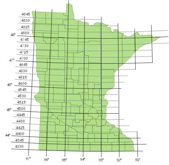
The Minnesota Project Coordinate System of NAD 27 (MNPCS), designed by MNDOT, consisted of 50 rectangular zones, each 1 degree of
longitude by 15 minutes of latitude, Figure M-8.
 |
|
Figure M-8 |
A zone was identified by abbreviated geodetic coordinates of its southeastern corner: longitude degrees and latitude degrees and 15 minute interval. For example, the southwestern-most zone is 974330 (97°, 43°30').
(b) Mathematics
Each zone was linked directly to the SPC system. A Combined Factor, CF, was determined from a zone's mean elevation and mean SPC grid factor. Because SPC coordinates were so large, origin offsets were selected to reduce their magnitude to a more convenient size. Zone coordinates were determined by dividing SPC coordinates by the CF and adding the origin offset. The CFs and origin offsets are published on MNDOT's Minnesota Project Coordinate System of NAD 27 page.
Ground to grid distance distortion did not exceed 1/20,000. This was sufficient to consider ground and grid distances the same for most surveys at the time .
(c) Counties
MNPCS rectangular zones did not coincide with jurisdictional boundaries nor did any county fall entirely within a singe rectangular MNPCS zone - most were located in parts of two or more zones. Distortions were controlled within a zone and extending the coordinate system beyond its boundaries would introduce greater distortion. A few of the larger and more populous counties used MNPCS's design methodology to create their own single or multiple zone systems.
(2) NAD 83: Minnesota County Coordinate Projections (MNCCP)
(a) Definition
Post-NAD 83, the 1°x15" rectangular zones were abandoned in favor of a projection-based coordinate system for each county. These county systems were not linked to the SPC and were a clean re-design.
(b) Design
The MNCCP, designed by University of Minnesota faculty and graduate students, used a Lambert conic or transverse Mercator cylindric projection based on a county's configuration. A special zone along Lake Superior's western shore used an oblique Mercator cylindric projection, Figure M-9.
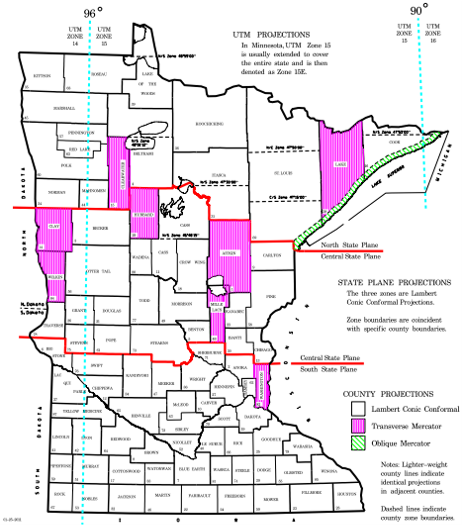 |
| Figure M-9 Minnesota County Coordinate System Source: http://www.dot.state.mn.us/surveying/pdf/mncoordsys.pdf |
There is no indication on the MNDOT website what was used for a maximum design distortion.
(c) Mathematics
An average ellipsoid height was determined for each county based on its mean elevation and geoid height.
- Lambert conic counties
A raised ellipsoid was created by increasing the GRS 80 ellipsoid semi-major axis by the height and the semi-minor axis by a proportional amount to maintain geometry as described in Section B.2.b(2).
Coordinate conversion and grid distance reduction distances are done with the conic projection equations in NOAA Manual NOS NGS 5 State Plane Coordinate Systems of 1983 using individual county parameters and semi-major axes listed on the NAD 83 Minnesota County Coordinate System page of the MNDOT website.
No mention is made about the latitude correction discussed in Section B.2.b(2). Hmm...
- Transverse Mercator cylindric counties
The height is not added to the GRS 80 semi-major axes prior to coordinate conversion. Instead, an Elevation Factor, EF, is defined for a county using the earth radius and its average ellipsoid height.
The EF is used to convert between county coordinates and those from the NOAA Manual NOS NGS 5 cylindric projection equations using county parameters. The parameters are listed on the NAD 83 MNCCS page.
c. Illinois NAD 83
The Illinois State Plane Coordinate System Committee (ISPCSC) recently (2021) developed the Illinois Coordinate System of 1983: 33 Zone Layer (ICS83: 33 Zone). As its name implies, it consists of 33 LDP grids covering the state of Illinois, Figure M-10.
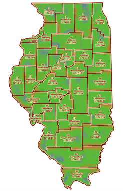 |
| Figure M-10 ICS83: 33 Zone Source: IL Geospatial Data Clearninghouse |
Zones were designed following NGS NATRF2022 LDP standards described in Section 6 of Procedures for Design and Modification of the State Plane Coordinate System of 2022 which, despite its name, also applies to LDPs. Near-ground grids are based on non-intersecting projections fit to the GRS 80 ellipsoid, similar to the condition shown in Figure M-4.
There are:
- Nineteen zones on conic projections: These use a single standard parallel conic projection whose equations differ from a two standard parallel conic used for SPC and other LDP systems.
- Fourteen zones on transverse cylindric projections
Reported grid-ground distortions are less than 20 ppm (= 1/50,000) over 99% of the state.
Basic information, parameters, and software are at the ICS83: 33 Zone page on the IL Geospatial Data Clearinghouse website.
d. Oregon NAD 83
Oregon begacn development of its Oregon Coordinate Reference Systems in the mid 2000's. A list of 20 best practices goals were estbliahed to guide development of the zones. Among the more critical were
- 1/100,000 maximum ground-grid distortion
- Use conventional conic, transverse cylindric, and oblique cylindric projections
- No ellipsoid modification
- Referenced to the NSRS
- Zone extents would not be jurisdictionally limited
- Publication of a Handbook and User Guide
- Involve vendors and developers so zone parameters would be included in commercial software.
Because of Oregon's varying terrain, 39 overlapping zones were developed, Figure M-11.
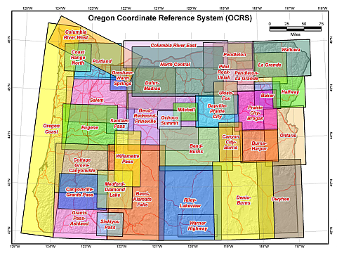 |
| Figure M-11 Oregon Coordinate Reference Systems |
More information is on the Oregon Coordinate Reference System website.
BTW - Oregon uses the International Foot definition to relate Imperial and Metric linear systems.
e. Wisconsin NAD 83
(1) Wis County Coordinate System (WCCS)
Wisconsin was another early adopter of statewide LDPs although it was after the NAD 83 (91) adjustment. In the early 1990s the Wis Dept of Transportation (WIDOT) contracted for the development of an LDP for each of the state's 72 counties. The project was completed in 1993 and named the Wisconsin County Coordinate System (WCCS).
Maximum allowable ground-to-grid distortions of 1/30,000 in rural areas and 1/50,000 in urban areas were specified. An ellipsoid height was determined for each county based on its median elevation and average geoid height. The ellipsoid height was added to both axes of the GRS 80 ellipsoid to create a parallel raised ellipsoid for the county. Depending on county configuration, a conic or cylindric projection was used to create the grid system.
Due to their size and/or elevation variation, some counties were combined into a single coordinate system and still met the distortion specifications. Figure M-12 is a map of Wisconsin counties. Counties shown in white have their own coordinate systems; counties that share a coordinate system are shown in the same color.
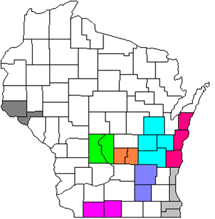 |
| Figure M-12 Wis County Coordinate Systems |
WCCS consisted of 59 systems covering 71 counties. Jackson County in west-central Wisconsin is not part of WCCS: the County Surveyor created a system prior to WCCS implementation.
County coordinates were computed directly from the NOAA Manual NOS NGS 5 projection equations using the county's parameters and raised ellipsoid data - no other computations or modifications are needed. Parameters and a distortion analysis for each county is available on the Wisconsin State Cartographer's Office (SCO) website.
WCCS system was immediately adopted by most counties and major municipalities on which to build their geographic information systems (GIS).
(2) Wisconsin Coordinate Reference System (WisCRS)
Although WCCS was popular and widely used, some GIS users reported position errors when combining data from different coordinate systems. This was the software issue described in Section B.4: some software treated coordinate conversion as a datum-to-datum transformation instead of a rigorous conversion because of the raised ellipsoid parameters. The Wisconsin Land Information Association created a Task Force to examine the issue and identify ways it could be resolved.
After a series of meetings and with input from diverse groups of stakeholders, the Task Force decided the county LDPs should be redesigned and referenced directly to the GRS 80 ellipsoid. Moreover, because so many users had data based on WCCS, the new systems had to be accuracy compatible: maximum position difference could not fall outside ±5 mm. This required new parameters and using a single-parallel projection for conic systems.
The redesigned coordinate systems were completed in 2009. WisCRS is actually the collection of all the formal coordinate systems in Wisconsin, of which the county LDPs are a subset.
Parameters and a distortion analysis for each county is in the second edition of the Wisconsin Coordinate Reference Systems handbook on the SCO website.
More information including equations for a single-parallel conic projection, county-by-county WCCS-WisCRS position comparisons, and software utilities are on the SCO's Coordinate Reference Systems webpage.
Although WisCRS county systems were intended to replace WCCS, both sets of county systems generally appear in many software packages.