2. Smaller and closer
A "perfect" grid system would be one where ground and grid distances were identical. This is impossible because of the earth's shape, but it is possible to make the differences smaller than 1/10,000. How small depends how the system is designed.
a. Smaller Area
SPC and UTM are both regional systems covering relatively larges areas and their coordinate magnitudes reflect that. Most mapping and surveying activities occur over smaller expanses.
In Chapter C, we saw that smaller distortions can be achieved by projecting a smaller area. While that may minimize ellipsoid to grid distortion, we still have to contend with elevation.
b. Near the Surface
To further minimize overall ground to grid distortion, the projection can be brought closer to the earth's surface. This is referred to as a Low Distortion Projection, LDP, Figure M-2.
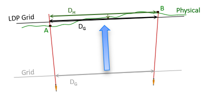 |
| Figure M-2 Low Distortion Projection |
The projection can be fit two different ways.
(1) Fit to GRS 80 Ellipsoid
Fitting to the GRS 80 ellipsoid means the projection surface may not intersect (tangent or secant) the ellipsoid, Figure M-3.
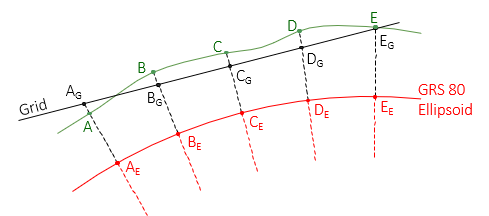 |
| Figure M-3 Projection Fit to Existing Ellipsoid |
Zone parameters are defined differently than for intersecting projections and projection equations must be modified.
(2) Fit to a New Ellipsoid
The projection can be fit conventionally (tangent or secant) to a new ellipsoid which is brought closer (raised) to the surface. This brings grid scale very close to one and balanced across the area, Figure M-4.
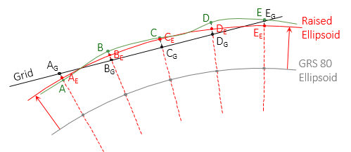 |
| Figure M-4 Projection Fit to New Ellipsoid |
Cylindric and conic projection equations are not dependent on a specific ellipsoid. Any ellipsoid can be used since its parameters (a, e, e', etc) are included in the direct and inverse conversion equations. That simplifies ellipsoid customization.
The easiest way to create a raised ellipsoid is to base it on the GRS 80 ellipsoid. A design height is determined from an area's elevation and geoid height behavior and used to bring an ellipsoid closer to the surface. The design height can be applied one of two ways.
(a) Constant height
Adding the same value, d, to both GRS 80 axes creates a parallel ellipsoid. The normal to the GRS 80 ellipsoid at a point position is also normal to the raised ellipsoid making the geodetic latitude for both surfaces the same, Figure M-5 .
 |
| Figure M-5 Constant Design Height |
| d | design height; f(elevation, geoid height) |
| Φ | GRS 80 ellipsoid latitude |
| ΦR | Raised ellipsoid latitude |
The normal is in the same meridian for both ellipsoids so the geodetic longitude is not affected. Because the geodetic coordinates do not differ, errors are not introduced between the LDP grid and GRS 80 geodetic positions.
Although parallel, the ellipsoids do not have the same geometric properties - their flattening, first and second eccentricities differ. In general this shouldn't be a problem because the projection equations include ellipsoid parameters, but some people find this disconcerting which is why differential heights can be used instead.
(b) Differential height
To keep ellipsoid relationships the same requires increasing both axes by different amounts. The design height, da=d, is added to the semi-major axis. The semi-minor axis is increased by a proportionally smaller height, db.
OK, so the ellipsoid geometry is maintained but a new problem appears: the normal to the GRS 80 ellipsoid is not normal to the raised ellipsoid, Figure M-6.
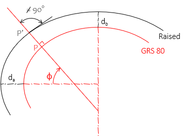 |
| Figure M-6 Differential Design Heights |
| da | design height; f(elevation, geoid height) |
| db | f(da, a, e) |
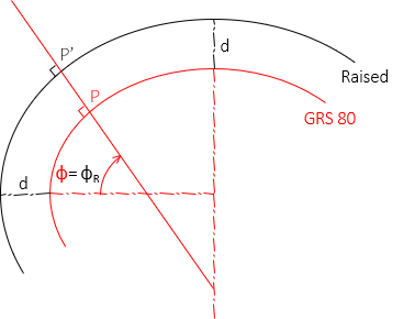
Latitude is the angle between the semi-major axis and the normal to the ellipsoid. A new normal at the raised point's position intersects the semi-major axis at a different geodetic latitude, Figure M-7.
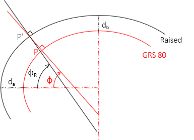 |
| Figure M-7 Different Latitudes |
The geodetic longitude is not affected since both normals are in the same meridian.
Because the two ellipsoids are rigorously connected, the latitude difference can be mathematically determined (it is a function of the latitude). This difference must be accounted for to prevent conversion errors between the LDP grid and GRS 80 geodetic positions.
c. Ground is Grid, Grid is Ground
On a carefully created LDP, grid and ground distances can be considered the same. There will be some distortion, but it will be much less than the typical distortion in an SPC or UTM system. This simplifies surveying measurements as well as mapping and GIS applications. For high accuracy needs, the remaining distortion can be compensated mathematically.
d. Software Issues
Until recently, LDP adoption, has been relatively limited; a few key implementations are discussed in the next section. Early LDP adopters encountered software problems: some converted positions incorrectly when encountering non-GRS 80 ellipsoid parameters, thinking it was a different datum. The software was not set up to recognized that LDPs referenced to raised ellipsoids had a rigorous connection between grid and geodetic coordinates and a datum change was not involved. It would apply an approximate datum-to-datum transformation instead of using the projection equations with the appropriate ellipsoid and zone parameters. This would introduce position errors, substantial in some cases. On-the-fly software would do this without the user's knowledge, other might stop and ask a confused user what to do.
This was slowly addressed by developers who incorporated existing LDPs in their software. Later LDP designs moved away from raised ellipsoids to fit ground level projections to the GRS 80 ellipsoid.