3. Distortions
a. Types of distortions
All the issues in Figure C-8 are the result of two types of distortion acting either alone or in concert: direction and distance
(1) Direction
Bending meridians change directions of lines referenced to them. The angle between a grid meridian and a true meridian is the mapping angle or convergence, γ. Figure C-9 shows one of the true meridians from Figure C-8 and a corresponding grid meridian. Because of how the true meridian is projected, its relationship to Grid North varies along its entire length. The direction of line AB can be converted from True to Grid if the convergence is known at point A.
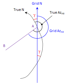 |
| Figure C-9 Direction Distortion |
(2) Distance
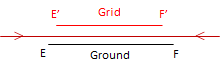
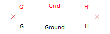
Except where it tears, the orange peel either stretches, shrinks, or doesn't change when it is flattened. Where it stretches, distances become longer; where it shrinks they become shorter; where it doesn't change, distances stay the same. This is called scaling, Figure C-10.
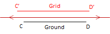 (a) Stretch: Scale > 1 |
 (b) Shrink: Scale < 1 |
 (c) No change: Scale = 1 |
| Figure C-10 Distance Distortion |
b. Correcting distortions
Can distortions be eliminated or do we have to live with them? It depends, to a certain extent, on what our needs are. It would be best if we got rid of or minimized them before they become a problem.
(1) Mathematical compensation
The 2D plane is a simple mathematical surface. If our orange was a perfect sphere, it would also be a mathematical surface. Both surfaces can be rigorously related with equations so distortions could be determined based on location. For example, if we know the latitude and longitude of point A in Figure C-9, we could compute the orientation of True North and from that the convergence angle. The math may be complex and involved, but it is possible.
(2) Project a smaller area
The biggest contributor to the distortions in Figure C-8 is attempting to cover the entire globe on a single 2D coordinate system. It's apparent that some areas have less distortion because they are closer to the projection center.
Projecting a smaller area reduces distortions. In Figure C-11(a), a smaller part of the Earth is projected, Figure C-11(b) shows direction distortion.
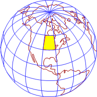 (a) Projection area |
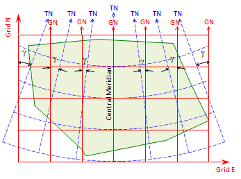 (b) Direction distortions |
| Figure C-11 Small Area Projection |
Dashed blue lines are true meridians. In the center of the projection, Grid and True North coincide - this is the Central Meridian (CM). Convergence increases moving east and west from the CM.
Distortions are smaller and more uniform.then projecting the entire Earth.
If a smaller area is projected, Figure C-12(a), its maximum distortions are even smaller, Figure C-12(b).
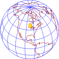 (a) Projection area |
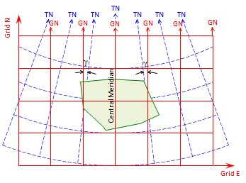 (b) Direction distortions |
| Figure C-12 Smaller Area Projection |
Distance distortion is also reduced as the projection area becomes smaller (if the area becomes small enough, we're back to Plane Surveying).
(3) Both
Projecting a smaller area reduces distortions but they are still present in the grid system. If the remaining distortions are too large for our purposes, then we can remove them mathematically.
But before we can do either, we need a mathematical connection between the Earth and the grid.