C. A Perfect 2D Grid?
1. Defining a Grid Coordinate System
A grid coordinate system must be carefully designed to ensure that:
- grid and horizontal ground distances match
- grid and horizontal ground angles match.
These, in turn, preserve shape and area of measured quantities.
An "ideal" grid coordinate system should have these three characteristics:
a. Orthogonal
The system consists of two reference axes are right angles to each other, Figure C-1
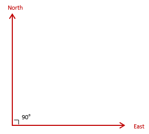 |
| Figure C-1 Reference Axes |
These define Grid North and Grid East for the system.
b. Parallel meridians
All meridians are parallel with the North reference axis, Figure C-2, with no convergence.
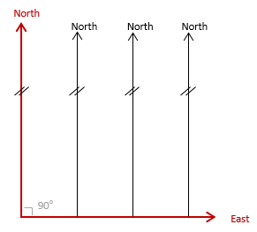 |
| Figure C-2 Parallel Meridians |
Forward and back grid directions always differ by exactly 180°.
c. Uniform scale
A linear unit is the same physical length regardless its orientation, Figure C-3.
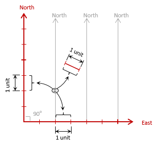 |
| Figure C-3 Uniform Scale |
2. 3D to 2D
a. You sat toe-may-toe, I say toe-mah-toe...
Although we've defined an ideal reference system, we still have a problem: projecting the 3D Earth into a 2D plane.
The tomato in Figure C-4 represents the Earth and the 2D plane the coordinate system.
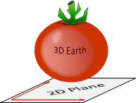 |
| Figure C-4 Earth and Plane |
What happens when we project the tomato into the plane, Figure C-5?
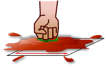 |
| Figure C-5 Project! |
The tomato must be distorted to fit into the plane. A 3D object cannot be projected into a 2D plane without introducing some distortions.
(Why a tomato? I was forced to eat them as a kid so I take advantage of every chance to exact vengeance on them.)
b. Orange Peel Map
Figure C-6 is an orange on which a globe has been copied. To project it into a 2D plane, the orange is carefully peeled, attempting to keep the peel in one piece although it will tear in a number of places.
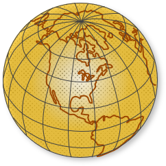 |
| Figure C-6 3D Globe |
It's laid it out flat creating an orange peel map, Figure C-7.
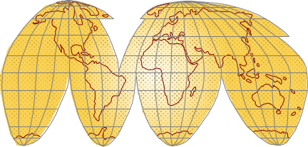 |
| Figure C-7 Orange Peel Map |
Some areas will lay flat without change. Others will stretch or shrink a little without tearing if the peel has some elasticity.
Adding North and East axes creates a grid coordinate system. Figure C-8 shows this and indicates a few of the many problems.
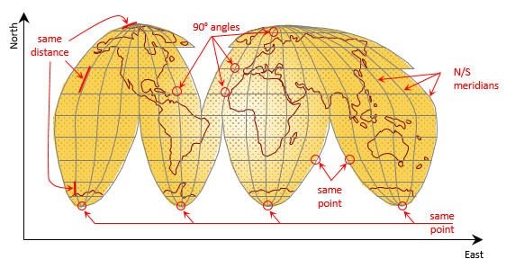 |
| Figure C-8 Distortions |
The angle between the equator at each meridian is very close or equal to 90°. North and south of the equator, angles between meridians and east-west lines differ from 90° by varying amounts.
Meridians uniformly converge to the two poles on the globe. When projected, along the equator they are equally spaced and roughly parallel. Going north and south, they are are bent into various shapes and do not converge on just two points.
A single point on the globe can have multiple physical representations on the coordinate system:
- The south pole is repeated four times, the north twice.
- Points along tear lines have two sets of coordinates
Shape and size are affected, the amount depending on location in the projected area. Note how much Anarctica's shape is affected versus Africa's .
3. Distortions
a. Types of distortions
All the issues in Figure C-8 are the result of two types of distortion acting either alone or in concert: direction and distance
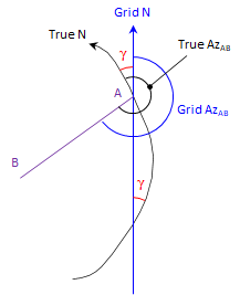
(1) Direction
Bending meridians change directions of lines referenced to them. The angle between a grid meridian and a true meridian is the mapping angle or convergence, γ. Figure C-9 shows one of the true meridians from Figure C-8 and a corresponding grid meridian. Because of how the true meridian is projected, its relationship to Grid North varies along its entire length. The direction of line AB can be converted from True to Grid if the convergence is known at point A.
 |
| Figure C-9 Direction Distortion |
(2) Distance
Except where it tears, the orange peel either stretches, shrinks, or doesn't change when it is flattened. Where it stretches, distances become longer; where it shrinks they become shorter; where it doesn't change, distances stay the same. This is called scaling, Figure C-10.
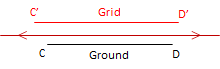 (a) Stretch: Scale > 1 |
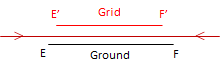 (b) Shrink: Scale < 1 |
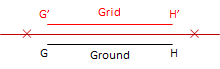 (c) No change: Scale = 1 |
| Figure C-10 Distance Distortion |
b. Correcting distortions
Can distortions be eliminated or do we have to live with them? It depends, to a certain extent, on what our needs are. It would be best if we got rid of or minimized them before they become a problem.
(1) Mathematical compensation
The 2D plane is a simple mathematical surface. If our orange was a perfect sphere, it would also be a mathematical surface. Both surfaces can be rigorously related with equations so distortions could be determined based on location. For example, if we know the latitude and longitude of point A in Figure C-9, we could compute the orientation of True North and from that the convergence angle. The math may be complex and involved, but it is possible.
(2) Project a smaller area
The biggest contributor to the distortions in Figure C-8 is attempting to cover the entire globe on a single 2D coordinate system. It's apparent that some areas have less distortion because they are closer to the projection center.
Projecting a smaller area reduces distortions. In Figure C-11(a), a smaller part of the Earth is projected, Figure C-11(b) shows direction distortion.
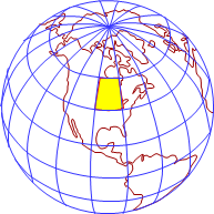 (a) Projection area |
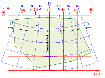 (b) Direction distortions |
| Figure C-11 Small Area Projection |
Dashed blue lines are true meridians. In the center of the projection, Grid and True North coincide - this is the Central Meridian (CM). Convergence increases moving east and west from the CM.
Distortions are smaller and more uniform.then projecting the entire Earth.
If a smaller area is projected, Figure C-12(a), its maximum distortions are even smaller, Figure C-12(b).
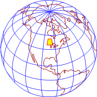 (a) Projection area |
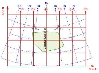 (b) Direction distortions |
| Figure C-12 Smaller Area Projection |
Distance distortion is also reduced as the projection area becomes smaller (if the area becomes small enough, we're back to Plane Surveying).
(3) Both
Projecting a smaller area reduces distortions but they are still present in the grid system. If the remaining distortions are too large for our purposes, then we can remove them mathematically.
But before we can do either, we need a mathematical connection between the Earth and the grid.