5. TIN
a. Triangulation
A TIN is a network of non-overlapping triangles connecting data points. Each triangle defines uniformly sloped interpolation paths along its sides, Figure E-14(a). The triangle is a 3D planar surface defined by each vertex position, Figure E-14(b).
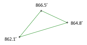 (a) Top View |
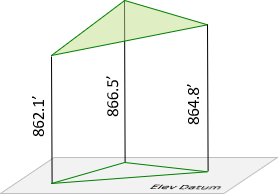 (b) Perspective View |
| Figure E-14 Data Triangle |
|
Figure E-15 Shows 1 ft interval elevations interpolated along triangle sides.
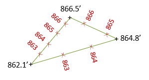 (a) Top View |
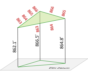 (b) Perspective View |
| Figure E-15 Interpolated Elevations |
|
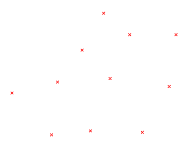
Because each is a planar surface, triangles cannot overlap. Figure E-16(a) is a data point set; Figure E-16(b) is a set of triangles connecting the data points.
 |
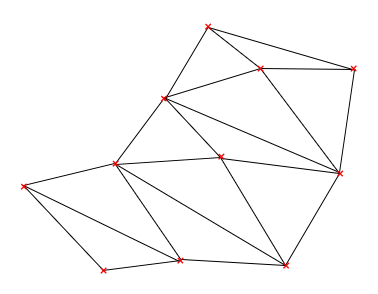 |
| (a) Data Points | (b) TIN |
| Figure E-16 TIN Creation |
|
Various combinations of non-overlapping triangles can be constructed. How do we decide which to use? An equilateral triangle is geometrically strongest, however data distribution doesn't always allow these to be uniformly created. Manual TIN creation builds the network visually - what looks strongest. Software uses algorithms to analyze different networks and select the geometrically strongest.
But both can fall flat on their face if they don't account for particular terrain features.
b. Breaklines
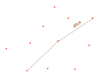
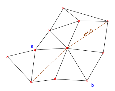
There are topographic features which affect surface model configuration. These must be included or the terrain model will be incorrect. A ditch runs through the data set in Figure 17(a). Figure 17(b) shows what happens if the ditch is ignored.
 |
 |
| (a) Ditch | (b) Interpolation Issue |
| Figure E-17 Topographic Feature |
|
Points a and b are on opposite sides of the ditch. Because the TIN connects them with a triangle side, it treats the ground as uniformly sloped between them. The ditch disappears between points a and b. The same happens wherever a triangle side crosses the ditch, which happens five times in Figure E-17(b).
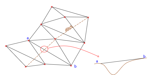
Interpolation should be forced along the ditch instead of across it. The TIN is reconfigured so successive ditch line segments form one common side of two adjacent triangles, Figure E-18.
 |
| Figure E-18 Interpolating Along the Ditch |
The TIN is created taking into account the ditch feature as a breakline. A breakline is a feature whose integrity must be maintained because it affects the terrain model. Feature examples that should be defined as breaklines include pavement edges, building footprints, ridges, waterways, etc. Breaklines can be man-made or natural, linear or area features.