2. Contour Properties
Because they represent real phenomena, mapped contour lines cannot do what real ones can't. This sounds simple, but basic errors are sometimes made creating contours manually or digitally.
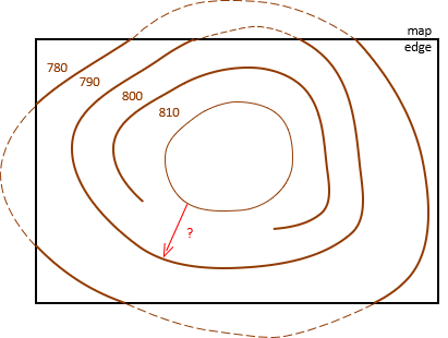
a. Closure
A contour line must eventually close back on itself. A contour line cannot just end or dangle. In Figure D-9 the red line cannot go from an 810 ft elevation to 790 ft without going through 800 ft.
 |
| Figure D-9 Contour Closure |
The only time a contour line can "end" is when it reaches the map edge. Our perspective of the line is limited by the map extent; the contour continues, shown dashed in Figure D-9.
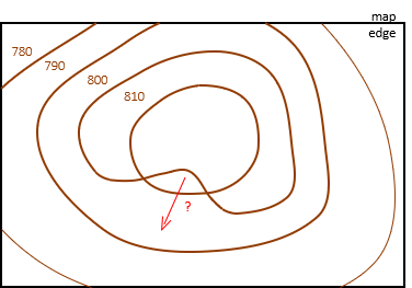
b. Crossing
Contour lines generally cannot cross, Figure D-10.
 |
| Figure D-10 Crossing Contours |
This causes a few dilemmas. The red line starts at elevation 800 ft, goes up to 810 ft, then to down to 790 ft without passing through 800 ft again. Also, both points where the lines cross have two elevations separated by 10 ft.
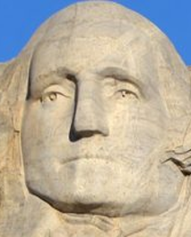
What about overhangs, like George Washington's nose and chin on Mount Rushmore, Figure D-11?
 |
| Figure D-11 George Washington |
Those are special and relatively isolated conditions. While contours can cross in those situations, the crossing contour is not technically visible and should be shown using a hidden line.
c. Coincidence
Except along man-made features, contour lines do not coincide for extended distances, Figure D-12.
 |
| Figure D-12 Coincident Contours |
Coincident contours indicate a perfectly vertical surface, something rarely occurring naturally. Due to weathering, even solid rock walls erode over time and lean causing contours to be close, but not coincident.
Man-made features, on the other hand, often have vertical surfaces and cause contours to run together.
For example, let's start with a naturally sloped area, Figure D-13.
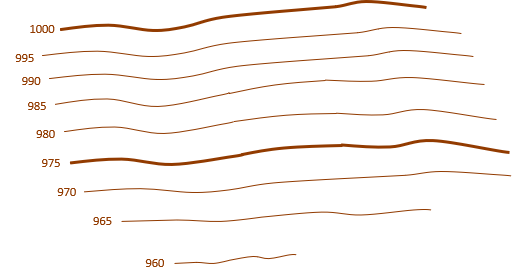 |
| Figure D-13 Original Slope |
A building with vertical walls is added, Figure D-14.
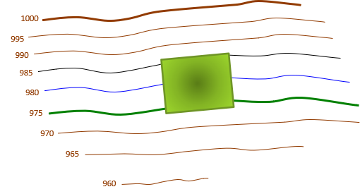 |
| Figure D-14 Building Added |
What happens to the 985 ft, 980 ft, and 975 ft contours? It looks like they end.
Figure D-15 is a perspective view of the area.
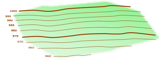 |
| Figure D-15 Original Slope Perspective |
To it is added the building, Figure D-16.
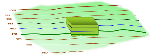 |
| Figure D-16 Building Added Perspective |
It can be seen in this view that the 985 ft, 980 ft, and 975 ft contours intersect the building's vertical walls, run around them, then continue along the terrain on the other side. Where the contours run along the building walls, they coincide on the map in Figure D-14.
d. Branching
Contour lines can't branch or split. In Figure D-17, the 808 ft contour indicates a knife-edge ridge at exactly 808 ft elevation.
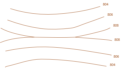 |
| Figure D-17 Branching Contours |
If the elevations were reversed, it would be a valley at an exact elevation. Neither condition is common in nature due to weathering. Contours usually closely straddle a ridge top (or valley). In Figure D-18, the ridge tops out higher than 808 ft.
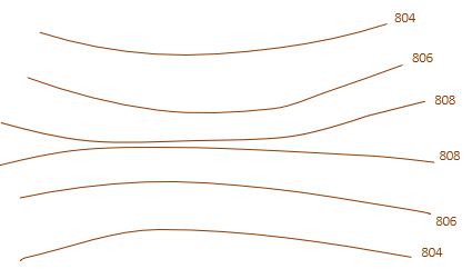 |
| Figure D-18 Straddling Contours |
f. Non-mathematical
Naturally occurring contour lines are neither mathematical curves nor are they straight and parallel. Along manmade features however, quite often the contours are mathematical and have uniform orientation.
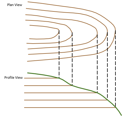
Figure D-19 shows the Plan (top) and Profile (front) Views of a ridge section.
|
|
| Figure D-19 Ridge Section |
A road will be run through the ridge. The Plan View in Figure D-20 shows the road location, the Profile View shows the road and its side slopes.
|
|
| Figure D-20 Proposed Road |
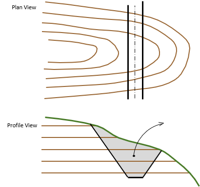
The side slopes have a uniform slope to provide bank stability. The grayed area shows the part of the ridge that must be excavated to construct the road.
Figure D-21 shows the ridge accounting for the road.
 |
| Figure D-21 Post-Construction Topography |
The excavated area in the Profile View removes part of the ridge changing the contours. The reconfigured contours are shown in the Plan View. They are uniformly spaced, because of the uniform side slopes, and parallel with the road.