2. Grid Directions and Angles
a. Convergence Angle
The angle from Geodetic North to Grid North is the Convergence, γ. In NAD 27 systems, it was called the mapping angle. Along the CM, Geodetic and Grid North coincide so there is no convergence. Convergence magnitude increases with distance east or west from the CM.
On a conic projection, Figure H-7, geodetic meridians (red) converge to the North Pole.
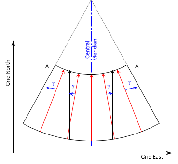 |
| Figure H-7 Conic Convergence |
The geodetic meridians on a transverse cylinder are more complex. On the grid they are curved lines converging to the North Pole, Figure H-8. The closer to the pole, the greater their curvature.
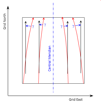 |
| Figure H-8 Cylindric Convergence |
Convergence is positive (+) east of the CM, negative (-) west, Figure H-9.
 |
| Figure H-9 Math Sign |
b.Projected lines
A geodetic line on the ellipsoid doesn't project as a perfectly straight line on the grid but is slightly curved. The curvature amount depends on the line's orientation. On a conic projection, Figure H-10(a), it is most pronounced for east-west lines and is concave toward the Central Parallel. On a transverse cylindric projection, the curvature is largest for north-south lines, Figure H-10(b), and is concave toward the Central Meridian.
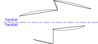 |
| (a) Conic Projection |
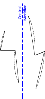 |
| (b) Transverse Cylindric Projection |
| Figure H-10 Projected Lines |
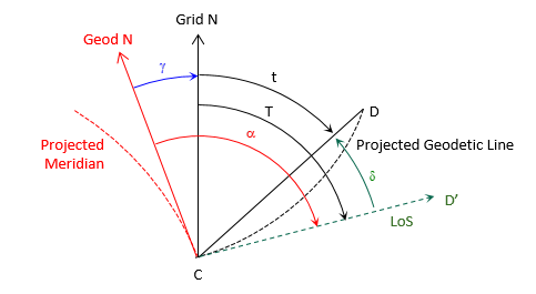
Geodetic meridians, being geodetic lines, also project slightly curved Figure H-11 shows a highly exaggerated depiction of the angle and direction relationships between straight and projected lines.
 |
| Figure H-11 Projected Line Relationships |
Geodetic north (solid red) on the grid is tangent to the projected meridian (dashed red) at the user's position, point C. When the observer sights point D, his line of sight (dashed green) is tangent to the projected line CD (dashed black). The angle between the line of sight and the straight chord CD is the arc-to-chord correction, δ.
Other elements in Figure H-11 are
T - grid azimuth of the projected line of sight
t - grid azimuth of the chord
α - geodetic azimuth of the projected line of sight
Equations H-7 and H-8 are the relationships between the various angles and azimuths.
| Equation H-7 | |
| Equation H-8 |
The arc-to-chord correction is also called the second term or (t-T) correction.
Equations H-9 and H-10 are arc-to-chord correction equations for conic projections.
 |
Equation H-9 |
 |
Equation H-10 |
Either can be used although Equation H-9 is set up for metric units.
Equations H-11 and H-12 are for transverse cylindric projections.
 |
Equation H-11 |
 |
Equation H-12 |
Either can be used although Equation H-11 is set up for metric units.
In the equations:
| δ12 | Correction for line 1 to 2; seconds |
| N1, E1 | Coordinates of from point 1 |
| N2, E2 | Coordinates of to point 2 |
| No | Northing at intersection of CM and Central Parallel |
| ro | Mean radius at origin latitude |
| Eo | CM Easting |
The Central Parallel of a conic projection is not the same as the Origin Parallel nor is it midway between North and South Standard Parallels. Its northing, No, is a constant but it must be computed from a zone's parameters.
Approximate coordinates can be used for both points in all four equations.
The mathematical sign on the correction indicates its direction: positive (+) is an angle to the right, negative (-) is an angle to the left.
If arc-to-chord corrections are significant they should be applied to the backsight and foresight lines of measured horizontal angles, Figure H-12, using Equation H-13,
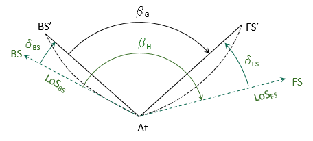 |
| Figure H-12 Corrected Angle |
 |
Equation H-13 |
where:
| βH | measured horizontal angle |
| βG | grid angle |
| δBS | backsight arc-to-chord correction |
| δFS | foresight arc-to-chord correction |
For most surveys,the corrections are generally smaller than angle measurement accuracy. To determine if they should be applied, compute the angle correction for a survey's the worst-case scenario; if it isn't significant, they can be ignored for all the angles. If that's the case, Equation H-7 becomes:
| Equation H-14 |
c. Forward and Back Directions
Because grid meridians are parallel, the forward and back grid azimuth of a line, Figure H-13, differ by exactly 180°, Equation H-15.
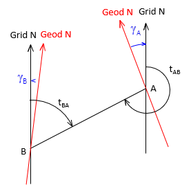 |
| Figure H-13 Forward and Back Grid Azimuths |
| Equation H-15 |
The line's forward and back geodetic azimuths, Figure H-14 , must account for the convergence difference at each end, Equation H-16.
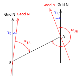 |
| Figure H-14 Forward and Back Geodetic Azimuths |
 |
Equation H-16 |