4. Secant Projections
a. Plane
Depending on its orientation, a secant tangent intersects the ellipsoid along a circle or ellipse, Figure D-10.
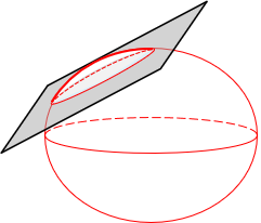 |
| Figure D-10 Secant Plane |
Inside the intersection scale is less than 1, outside greater than 1; along the intersection it is 1.
On the plane, Figure D-11, scale varies radially perpendicular to the intersection path, constant parallel with it.
 |
| Figure D-11 Secant Plane Scale |
Movement in any direction other than parallel with the intersection will cause scale variations. Line lengths don't change uniformly between the ellipsoid and grid. This limits plane projections to small areas or where larger variable distortions are tolerable. A plane projection is generally too restrictive for a regional survey-quality coordinate system.
b. Cone
A secant cone is oriented so its axis coincides with the polar axis, Figure D-12.
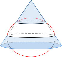 |
| Figure D-12 Cone Orientation |
It intersects the ellipsoid along two lines of latitude. When rolled out flat the two intersecting lines are arcs centered on the cone's apex. Because they are lines of latitude, Figure D-13, they run east-west and are called standard parallels. Geodetic meridians converge to the cone apex.
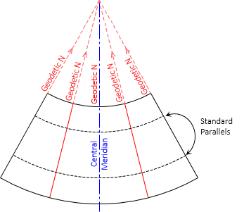 |
| Figure D-13 Conic Geodetic Meridians and Parallels |
Scale along standard parallels is 1; between them it is less than 1, outside greater than 1. Scale is constant along parallels of latitude and varies along geodetic meridians, Figure D-14.
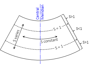 |
| Figure D-14 Conic Scale |
Conic projections are used for areas longer east-west than north-south. The most commonly used is the Lambert Conic projection developed by mathematician Johann Heinrich Lambert in 1792.
c. Cylinder
(1) Mercator Cylindric Projection
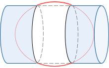
One of the first universally adopted cylindric projections was developed in 1569 by Gerardus Mercator. His projection was oriented with the cylinder's axis parallel with the Earth's rotational axis. The Mercator projection intersects the ellipsoid along two lines of latitude, one on each side of the equator, Figure D-14.
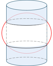 |
| Figure D-14 Mercator Cylindric Projection |
The projection was widely used for ship navigation, A ship sailing along a constant azimuth travels a curved path on the earth. On a Mercator projection, the ship's course is a straight line making navigation easier.
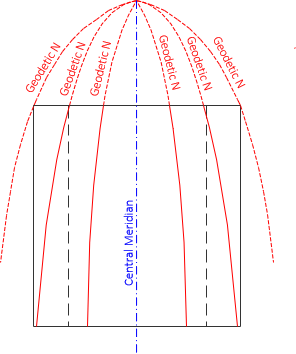
When rolled out flat the two intersection lines project as east-west lines, also called Standard Parallels. Instead of converging, geodetic meridians project parallel, Figure D-15
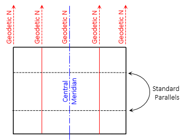 |
| Figure D-15 Cylindric Geodetic Meridians and Parallels |
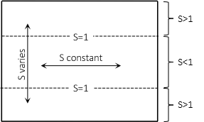
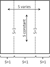
Scale along standard parallels is 1; between them it is less than 1, outside greater than 1. Scale is constant east-west and varies north-south along meridians. Figure D-16.
 |
| Figure D-16 Mercator Cylindric Scale |
Because geodetic meridians project parallel, object shapes can be substantially distorted. Minimizing scale requires keeping the Standard Parallels close to the equator. Distortion is least near the equator and gets much larger toward the poles.
A example Mercator cylindric projection is shown in Figure D-17.
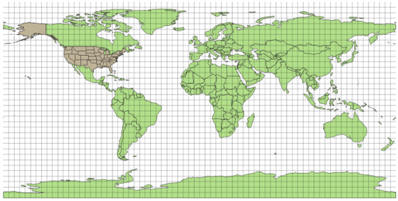 |
| Figure D-17 Worldwide Mercator Cylindric Projection |
Latitudinal lines and meridians are straight and equally spaced. Country shapes look "correct" near the equator. Moving north and south, shapes are "stretched" east-west because meridians do not converge. At the latitude of the United States,distortions exceed acceptable values for large scale mapping. A traditional Mercator cylindric projection is too limited for regional surveying coordinate systems.
(2) Transverse Mercator Cylindric Projection
Johann Heinrich Lambert (yup, the Cone-head) developed a version of Mercator's cylinder turned on its side, the Transverse Mercator cylindric projection, Figure D-18.
 |
| Figure D-18 Transverse Mercator Cylindric Projection |
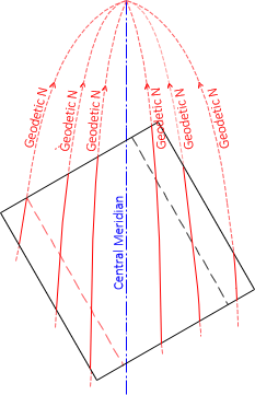
A transverse cylindric projection offers greater design flexibility and distortion control. It intersects the ellipsoid along two parallel ellipses. These ellipses are parallel with, and equidistant from, the central meridian. When rolled out flat, the two intersection lines project as straight lines, Figure D-19.
 |
| Figure D-19 Transverse Cylindric Meridians |
Geodetic meridians converge and, except for the central meridian, are curved. The degree of curvature depends on the latitude and size of the area.
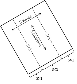
Scale is 1 along the intersection lines; it is less than 1 between and greater than 1 outside the intersection lines, Figure D-20.
 |
| Figure D-20 Transverse Cylindric Scale |
Scale is generally constant north to south and varies east to west. Because of this, a transverse cylindric projection is used for regions longer north-south than east-west.
(3) Oblique Mercator Cylindric Projection
A region's long axis can be oriented other than north-south or east-west. Conic and traditional or transverse cylindric projections may not fit the area well. In cases like this, an oblique cylindric projection can be used. An oblique cylinder is rotated so its axis direction is neither polar or equatorial, Figure D-21.
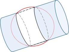 |
| Figure D-21 Oblique Secant Cylinder |
The oblique cylinder intersects the ellipsoid along two ellipses. When the cylinder is rolled out flat, the intersections project as straight lines. Geodetic meridian behavior is the same as a transverse cylindric project but rotated to the projection surface, Figure D-22.
 |
| Figure D-22 Oblique Cylindric Meridians |
Scale along the intersecting lines is 1; between it is less than 1, outside greater. Scale is constant in the rotated direction and varies perpendicular to it, Figure D-23.
 |
| Figure D-23 Oblique Cylindric Scale |