4. Combined Effect
Because they are related, Curvature and Refraction are generally treated as a single combined correction, however their effect is opposite.
Starting with a situation similar to the conditions in Figure I-1:
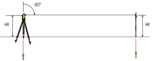 |
| Figure I-5 Plane Surveying Situation |
As we move the target further away, keeping its height constant and the LoS at 90° zenith angle, we get the situation in Figure I-6.
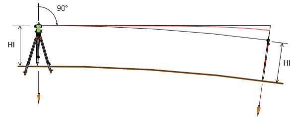 |
| Figure F-6 Curvature and Refraction |
-
- The blue line is the original LoS held at 90° zenith angle.
- The red line is the refracted LoS.
- The black line has a constant height (HI) along its length.
Figure I-7 is a closeup at the target end.
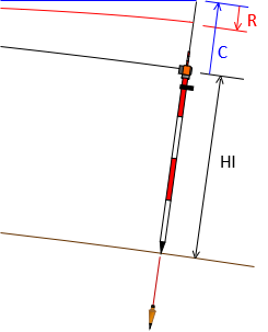 |
| Figure I-7 Curvature and Refraction at Target |
C is the curvature error. Instead of seeing the target, curvature makes us see above it
R is the refraction error. Refraction depresses the LoS making us see below where we should.
Combining Equations I-3 and I-4, the combined effect is Equation I-5.
| $\left( C+R \right) =0.0206F^2=0.574M^2$ | Equation I-5 |
Their combined effect at different distances is shown in Table I-3.
| Table I-3 | |
| Distance | C+R; feet |
| 100 | 0.000 |
| 200 | 0.001 |
| 300 | 0.002 |
| 400 | 0.003 |
| 500 | 0.005 |
| 1000 | 0.021 |
| 2000 | 0.082 |
| 4000 | 0.330 |
| 5000 | 0.515 |
e. Compensation
Does the combined curvature and refraction make a difference? For short distances it doesn't, for longer ones it does. But where is the area between plane and geodetic surveying where curvature and refraction should be taken into account? To a large degree it depends on the purpose of the survey.
Modern digital instruments can be set up to automatically apply curvature and refraction corrections. This should be enabled. If the error is significant, the measurement will be adjusted accordingly - there's no decision on the part of the surveyor. For non-digital instruments, the error may or may not be significant and it may be possible to compensate procedurally. We'll cover these in the respective instrumentation or measurement topic.