2. Curvature
Figure I-1 shows a typical plane surveying situation. The directions of gravity at the instrument at one end and target at the other are parallel.
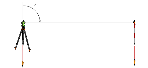 |
| Figure I-1 No Curvature |
To keep things simple, let's assume the instrument and target are the same height above a horizontal reference surface and the line of sight (LoS) between them is also horizontal. The zenith angle, Z, at the instrument is 90°00'00".
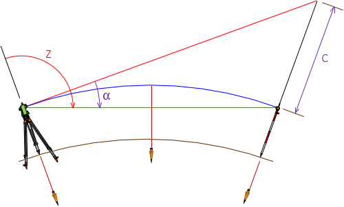
As distances get longer, directions of gravity begin to converge which makes the reference surface curved. The single horizontal black line between instrument and target in Figure I-1 separates into three different lines, Figure I-2 (the figure is exaggerated to clearly show the different components).
 |
|
Figure I-2 |
- The red line is the original LoS at the 90°00'00" zenith angle; it is perpendicular to gravity at the instrument location.
- The green line line is the new LoS between instrument and target; it is perpendicular to gravity only at its midpoint.
- The blue line is at a constant height above the reference surface and perpendicular to gravity along its entire length making it curved.
- Angle α is the zenith angle change due to curvature.
- Distance C the vertical distance caused by curvature.
Although the earth is a complex surface, we can approximate it with a constant radius spheroid. That works fine unless we're doing global measurements, but that's beyond the scope of the material here. What we want is reasonable math to deal with that gray area between plane and geodetic surveying.
Figure I-3 is Figure I-2 with some added lines and labels.
|
|
| Figure I-3 Curvature Geometry |
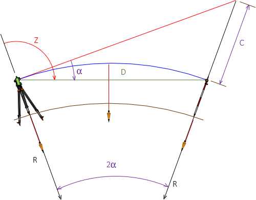
To determine α and C:
| $$ \alpha =\arcsin \left[ \frac{D}{2R} \right] $$ |
Equation I-1 |
| $$C=\frac{D^2}{2R\cos \left( 2\alpha \right)} $$ |
Equation I-2 |
D: Straight line distance from instrument to target; measured.
R: Earth radius; 20,906,000 ft or 6,372,200 m.
Most surveying textbooks give Equation I-3 for the vertical distance curvature error, C. It is an approximation for Equation I-2 and doesn't require computing angle α.
| $C=0.0239F^2=0.667M^2$ | Equation I-3 |
F: Distance in thousands of feet (eg,: for 2000 ft, F=2)
M: Distance in miles
How significant are the curvature angle and vertical errors? Table F-1 shows the results of Equations I-1 and I-2 at increasing distances.
| Table I-1 | ||
| Distance | α; seconds | C; feet |
| 100 | 0.5 | 0.000 |
| 200 | 1.0 | 0.001 |
| 300 | 1.5 | 0.002 |
| 400 | 2.0 | 0.004 |
| 500 | 2.5 | 0.006 |
| 1000 | 4.9 | 0.024 |
| 2000 | 9.9 | 0.096 |
| 4000 | 19.7 | 0.383 |
| 5000 | 24.7 | 0.598 |
Up to about 500 feet neither α or C are very large, but they become significant at longer distances.