I. Curvature and Refraction
1. What
The fundamental difference between plane and geodetic surveying is the latter takes into account the size and shape of the earth. However, there is no distinct point where surveying crosses from one classification to the other; there tends to be a gray area in between. This is because much of the technology we use today allows us to measure over larger areas than just a few decades ago.
Earth curvature and atmospheric refraction are two primary errors that must be taken into account when measurements become sufficiently long. Curvature and refraction affect any measurements dependent on an optical line of sight (LoS) or energy wave, which covers a lot of survey measuremetns. Because of this, we'll discuss them here and then refer back to this material in later topics.
2. Curvature
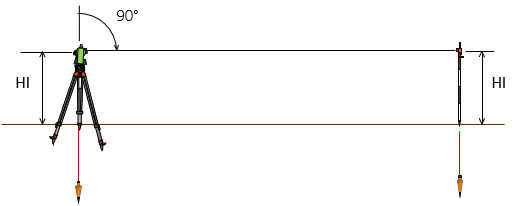
Figure I-1 shows a typical plane surveying situation. The directions of gravity at the instrument at one end and target at the other are parallel.
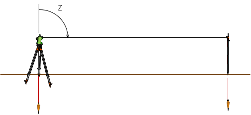 |
| Figure I-1 No Curvature |
To keep things simple, let's assume the instrument and target are the same height above a horizontal reference surface and the line of sight (LoS) between them is also horizontal. The zenith angle, Z, at the instrument is 90°00'00".
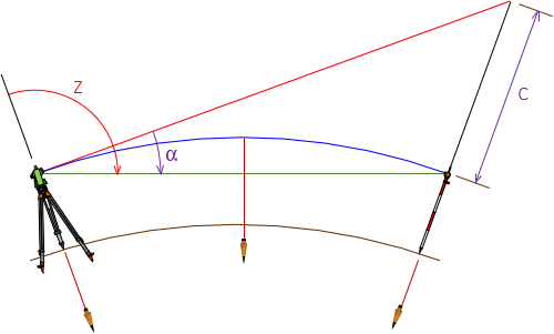
As distances get longer, directions of gravity begin to converge which makes the reference surface curved. The single horizontal black line between instrument and target in Figure I-1 separates into three different lines, Figure I-2 (the figure is exaggerated to clearly show the different components).
 |
|
Figure I-2 |
- The red line is the original LoS at the 90°00'00" zenith angle; it is perpendicular to gravity at the instrument location.
- The green line line is the new LoS between instrument and target; it is perpendicular to gravity only at its midpoint.
- The blue line is at a constant height above the reference surface and perpendicular to gravity along its entire length making it curved.
- Angle α is the zenith angle change due to curvature.
- Distance C the vertical distance caused by curvature.
Although the earth is a complex surface, we can approximate it with a constant radius spheroid. That works fine unless we're doing global measurements, but that's beyond the scope of the material here. What we want is reasonable math to deal with that gray area between plane and geodetic surveying.
Figure I-3 is Figure I-2 with some added lines and labels.
|
|
| Figure I-3 Curvature Geometry |
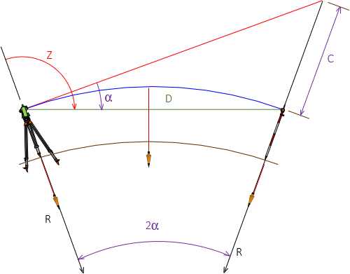
To determine α and C:
| $$ \alpha =\arcsin \left[ \frac{D}{2R} \right] $$ |
Equation I-1 |
| $$C=\frac{D^2}{2R\cos \left( 2\alpha \right)} $$ |
Equation I-2 |
D: Straight line distance from instrument to target; measured.
R: Earth radius; 20,906,000 ft or 6,372,200 m.
Most surveying textbooks give Equation I-3 for the vertical distance curvature error, C. It is an approximation for Equation I-2 and doesn't require computing angle α.
| $C=0.0239F^2=0.667M^2$ | Equation I-3 |
F: Distance in thousands of feet (eg,: for 2000 ft, F=2)
M: Distance in miles
How significant are the curvature angle and vertical errors? Table F-1 shows the results of Equations I-1 and I-2 at increasing distances.
| Table I-1 | ||
| Distance | α; seconds | C; feet |
| 100 | 0.5 | 0.000 |
| 200 | 1.0 | 0.001 |
| 300 | 1.5 | 0.002 |
| 400 | 2.0 | 0.004 |
| 500 | 2.5 | 0.006 |
| 1000 | 4.9 | 0.024 |
| 2000 | 9.9 | 0.096 |
| 4000 | 19.7 | 0.383 |
| 5000 | 24.7 | 0.598 |
Up to about 500 feet neither α or C are very large, but they become significant at longer distances.
3. Refraction
Atmosphere has density and an electromagnetic energy ray passing through it will be bent. That includes the LoS through an instrument's telescope. The denser the atmosphere, the more the LoS is bent.
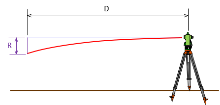
Atmosphere is generally densest near the ground and decreases with elevation. When sighting longer distances, our LoS starts at the instrument's density condition and is bent downward as it progresses towards the target, Figure I-4
|
|
| Figure I-4 Refraction |
The amount the LoS refracts from the straight line is not linear: at 200 feet it is not twice the refraction at 100 feet. Over short distances, the atmosphere density distribution is relatively uniform. At longer distances that is probably not true. Solar heating and weather fronts can cause anomalous atmospheric pockets disrupting the otherwise smoothly refracted path. Local heat waves, even over short distances, can randomly affect LoS displacements.
Basically, getting a strong handle on how refraction behaves is relatively difficult. Its overall effect on readings is relatively small, considerably smaller than curvature. In most computations, refraction error is taken as a percentage of earth curvature. It varies from 17% at sea level (dense atmosphere) to 7% in mountainous areas (less dense) with 14% used as a common overall factor. It's computed using Equation I-4; because the LoS is depressed, the equation is negative.
| $R=-0.0033F^2=-0.093M^2$ | Equation I-4 |
R: Refraction error (not Earth radius)
F: Distance in thousands of feet (eg,: for 2000 ft, F=2)
M: Distance in miles
Table I-2 shows the refraction displacement at select distances from 100 to 5000 ft.
| Table I-2 | |
| Distance | R; feet |
| 100 | 0.000 |
| 200 | 0.000 |
| 300 | 0.000 |
| 400 | -0.001 |
| 500 | -0.001 |
| 1000 | -0.003 |
| 2000 | -0.013 |
| 4000 | -0.053 |
| 5000 | -0.083 |
4. Combined Effect
Because they are related, Curvature and Refraction are generally treated as a single combined correction, however their effect is opposite.
Starting with a situation similar to the conditions in Figure I-1:
 |
| Figure I-5 Plane Surveying Situation |
As we move the target further away, keeping its height constant and the LoS at 90° zenith angle, we get the situation in Figure I-6.
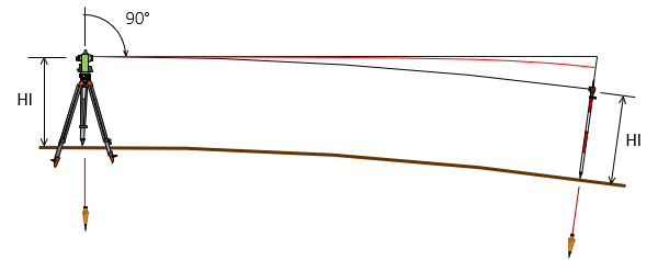 |
| Figure F-6 Curvature and Refraction |
-
- The blue line is the original LoS held at 90° zenith angle.
- The red line is the refracted LoS.
- The black line has a constant height (HI) along its length.
Figure I-7 is a closeup at the target end.
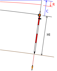 |
| Figure I-7 Curvature and Refraction at Target |
C is the curvature error. Instead of seeing the target, curvature makes us see above it
R is the refraction error. Refraction depresses the LoS making us see below where we should.
Combining Equations I-3 and I-4, the combined effect is Equation I-5.
| $\left( C+R \right) =0.0206F^2=0.574M^2$ | Equation I-5 |
Their combined effect at different distances is shown in Table I-3.
| Table I-3 | |
| Distance | C+R; feet |
| 100 | 0.000 |
| 200 | 0.001 |
| 300 | 0.002 |
| 400 | 0.003 |
| 500 | 0.005 |
| 1000 | 0.021 |
| 2000 | 0.082 |
| 4000 | 0.330 |
| 5000 | 0.515 |
e. Compensation
Does the combined curvature and refraction make a difference? For short distances it doesn't, for longer ones it does. But where is the area between plane and geodetic surveying where curvature and refraction should be taken into account? To a large degree it depends on the purpose of the survey.
Modern digital instruments can be set up to automatically apply curvature and refraction corrections. This should be enabled. If the error is significant, the measurement will be adjusted accordingly - there's no decision on the part of the surveyor. For non-digital instruments, the error may or may not be significant and it may be possible to compensate procedurally. We'll cover these in the respective instrumentation or measurement topic.