C. Horizontal Curves
1. Basic Concepts
a. General
While some alignments like an electrical transmission line can be designed with angle points at changes in horizontal direction, alignments for moving commodities with mass must have less abrupt transitions. This is accomplished by linking straight line segments with curves, similar to that in vertical alignments. However in this case the lines and curves linking them are in a horizontal plane.
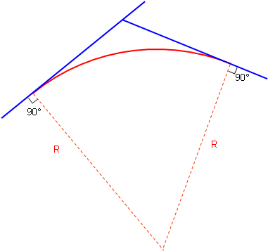
A simple tangent geometric curve is used to link the two lines. A curve is tangent to a line when its radius is perpendicular to the line, Figure C-1.
 |
|
Figure C-1 |
The two lines bounding the curve are generically referred to as tangents or tangent lines. The direction of a curve is either right or left based on the deflection direction between the tangents, Figures C-2 (a) and (b).
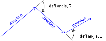 (a) Deflection Angles |
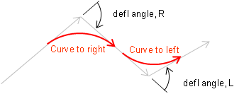 (b) Curves |
| Figure C-2 Curve Direction |
|
In roadway design horizontal geometry differs from vertical because a driver is responsible for guiding a vehicle from the first tangent to the second one. This requires turning a steering wheel changing the car's direction. Ideally this would be a smooth action to cause minimal discomfort: once into a curve, the steering angle would be maintained until the tangent is reached.
Two different mathematical arcs can be used for horizontal curves, either singularly or in combination: a circular arc and a spiral arc.
b. Circular arc
A circular arc has a fixed radius which means a driver doesn't have to keep adjusting the steering wheel angle as the car traverses the curve. It is a simple curve which is relatively easy to compute, Figure C-3.
 |
| Figure C-3 Circular Arc |
Its primary disadvantage is that the constant curvature must be introduced immediately at curve's beginning. That means a driver would have to instantaneously change the steering wheel angle from 0° to full or the car would overshoot the curve. A similar condition exists ate the curves's end. The higher the vehicle speed and the sharper the curve, the more pronounced the effect.
c. Spiral arc
A spiral has a constantly changing radius, Figure C-4. At the spiral's beginning, its radius is infinite; as the vehicle progreeses into the curve, the spiral radius decreases. A spiral provides a more natural direction transition - the driver changes the steering wheel angle uniformly as the car traverses the curve.
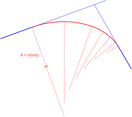 |
| Figure C-4 Spiral Arc |
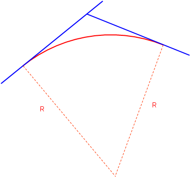
Attaching a second sprial with reversed radius change creates an entrance-exit spiral condition where the driver gradually increases then gradually decreases steering wheel angle, Figure C-5.
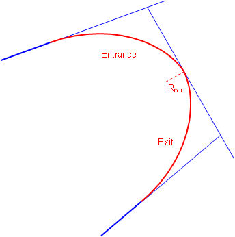 |
| Figure C-5 Combined Spirals |
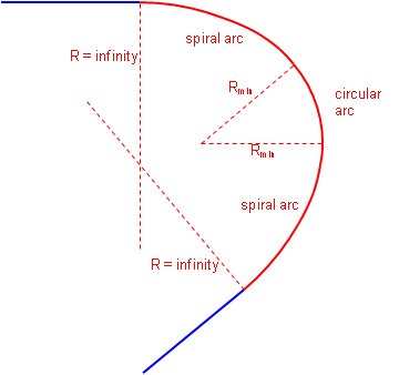
A circular arc can be combined with two spirals, Figure C-6.
 |
|
Figure C-6 |
Combined spirals and spiralled horizontal curves, in conjunction with superelveation, help balance centrifugal forces. For a constant velocity, as the radius decreases the centrifugal force increases. A spiral allows superelevation to be introduced at a uniform rate allowing it to offset increasing centrifugal force. In theory, there exists an equilibrium velocity at which a vehicle could travel from one tangent through the spirals and curve to the second tangent safely even if the road were completely ice covered.
Railroad alignments typically use spiral horizontal curves because of their force balancing nature. Because of the wheel flange to rail connection, a train moving around a curve exerts a force directly to the rails (unlike a vehicle's tire-pavement connection which can devolve into a skid). A rail line laid out with a circular arc would shift to a spiral configuration after a train has run through it a number of time at transport speed.
The traditional disadvantage of a spiral is that it is complex to compute, although that has been largely negated by software. While still used for railways, in high speed highway design using long flat circular arcs minimizes the tangent to curve transition so spirals aren't as critical. They can be useful in low speed situations where there is a large direction transition. We'll examine spiral geometry and application in a later section.