Chapter E. Basic Gravity Measurement
1. Geoid Modeling
There is a lot that goes into creating a model of a surface that doesn't physically exist. Its configuration and location must be inferred through physics principles, geodynamics, celestial influence, dynamic forces, etc. Based on how they were created, neither NGVD 29 nor NAVD 88 are true representations of either MSL nor the geoid.
It all depends on gravity and the ability to measure and monitor it.
In the chapter on Earth surfaces we said the geoid changes over time due to the Earth's internal dynamics. Remeasuring and/or monitoring gravity as well as increasing the density of gravity measurements will ultimately lead to better geoid definition.
Expanded gravity measurements will be used to develop GEOID2022 which will be a critical component of the North American Terrestrial Reference Frame of 2022 (NATRF2022) and North American-Pacific Geopotential Datum of 2022 (NAPGD2022)
In this chapter we'll touch on some basic gravity measurement concepts to introduce terminology and some programs in progress. There is considerably more depth to this subject than covered here. As the lead agency NGS has many publications and presentations on gravity measurement and geoid modeling on its website. The reader is encouraged to explore their resources at the NGS website.
2. Gravity Station
A gravity station, Figure E-1, is a physical location at which absolute gravity has been measured. Most surveyors will never use a gravity station directly but it is important for geoid modeling and controlling further gravity measurements.
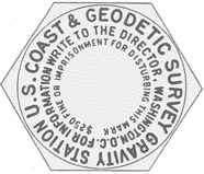 |
| Figure E-1 Standard Gravity Station Mark |
The units of gravity are mgal. A gal (named in honor of Galileo) is one centimeter per second squared: 1 cm/sec2. A mgal is a milligal, one thousandth of a gal
3. Early Measuring Devices
a. "England Swings Like a Pendulum Do"1
1 England Swings, composed and sung by Roger Miller, 1965
For about 100 years, beginning c1870, the primary device used to measure gravity was pendulum-based. The first were simple devices with a weight (bob) at the end of a free-swinging rod suspended on a knife-edge fulcrum. The pendulum's period, the time to swing from one side to the other and back again, was affected by gravity - the greater the gravity the shorter the period. Figure E-2 shows the general behavior of a pendulum for half a period, T/2.
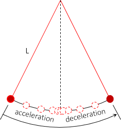 |
| Figure E-2 Simple Pendulum |
Gravity is determined from Equation E-1.
 |
Equation E-1 |
Early pendulums were made of non-magnetic brass, which has a relatively high coefficient of thermal expansion making it very temperature sensitive. Later devices were made of invar with a coefficient less than 10% that of brass. Free swinging in the air affected the pendulum so the rod and bob were encased in vacuum.
Figure E-3 is a typical recording system.
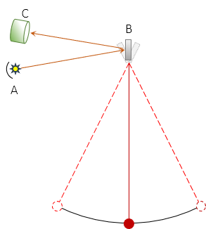 |
| Figure E-3 Recording |
Light emitted from a source, A, is reflected from a mirror, B, which is attached to and pivots with the pendulum rod. Twice during the pendulum period, when the bob is at its lowest point, the reflected light is directed at a recording device. This continues over a measured time interval. Using the time interval and number of recording hits, T can be determined then substituted in Equation E-1 to compute gravity.
Initially the largest error was time. Before radio broadcasts, time was established in the field by astronomic observations, a lengthy affair. As time determination technology evolved it became a smaller error.
Using a pendulum device, land-based gravity determination was able to reach an accuracy under 10 mgal.
b. Gravimeter
Although around since the late 17th century, gravimeters didn't come into widespread use until the 1950s. Gravimeters are based on the mechanical properties of a spring: a spring expands or contracts in direct proportion to the mass it supports, Equation E-2.
 |
Equation E-2 |
lo: initial spring length
m: mass
g: gravity
k: spring constant
l: final spring length
Figure E-4 is a conceptual schematic of a very basic gravimeter.
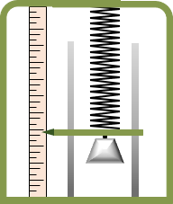 |
| Figure E-4 Gravimeter |
A fixed mass is attached to a spring and allowed to freely hang. Any attached support must allow friction-free vertical movement of the mass. A measuring system is needed to read and record spring length or length change.
There are different spring-based gravimeter designs, from simple devices as in Figure E-4 to more complex versions with weights mounted on pivoting levers. Each design addresses a particular disadvantage or environmental condition. For example, a simple device with an un-dampened system can take a long time to stabilize after being moved. Shipboard gravimeters require a different design and mounting so ship motion has minimal effect on gravity readings.
Depending on the design and implementation, gravimeters were able to achieve accuracy under 6 mgal.
4. Contemporary Gravity Measurement
Technology has evolved quite a bit in the last few decades causing maturation of some traditional measurement devices and creating new ones. One of the biggest changes is that measurements aren't limited to terrian-based instruments. Air- and space-borne systems allow greater area coverage than manual point-by-point measurement.
a. Absolute v Relative
There are many gravity data users with diverse accuracy and coverage requirements. Most try to locate and identify subsurface activity which affects gravity in a particular way. Surveyors, on the other hand, collect gravity data to relate to and refine the geoid model.
Absolute gravity measurements is the gravity at a point while relative is between points. Consider gravity stations as the control network for other gravity measurements, much like bench marks are for a leveling circuit. Control is established to a higher level of accuracy than are the surveys which use it. Establishing control often requires special equipment and/or procedures. Such is the case with gravity measurements.
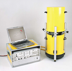
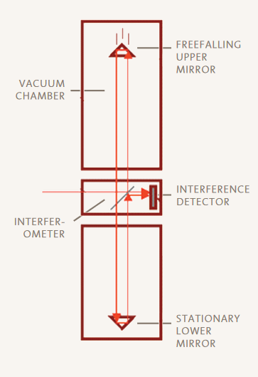
Absolute gravimeters are either pendulum or free-fall instruments, A free-fall instrument measures the time it takes an object to fall a specific distance (was the apple bonking Sir Isaac Newton the first gravimeter?). An instrument used by the NGS is the Micro-g LaCVoste A10 gravimeter, Figure E-5(a). It uses a laser interferometer to monitor a mirror dropped in a vacuum, Figure E-5(b).
 |
 |
| (a) | (b) |
| Figure E-5 Micro-g LaCVose A103 |
|
3 Manufacturer's website: https://microglacoste.com
To establish a gravity station requires 30-60 hours of observations, more if site has highly active gravity.
Absolute instruments can achieve an accuracy of ~1 mgal which corresponds to an elevation difference of about 0.01 ft. Besides determining point gravity, absolute measurements can be used to monitor gravity change at a point.
Because they are used to determine gravitational force at any location on Earth, absolute gravimeters need a large measuring range and must maintain their accuracy throughout the range.
Most relative gravimeters are based on the mass-spring concept, though more sophisticated than earlier versions. They are simpler than absolute instruments because they need only measure the gravity difference between locations which does not require a large measuring range.
b. Airborne Gravity Measurement
A gravimeter mounted in an aircraft provides the ability to measure gravity over large swaths of area. It is an excellent way to fill coverage gaps in terrestrial and shipboard networks. It uses relative gravimetric measurement system.
Figure E-6 is the NGS' relative meter jet platform.
 |
| Figure E-6 NGS Airborne Gravimeter System4 |
4 Airborne Gravity Processing 101, NGS Workshop, Preaux
In addition to the gravimeter, the aircraft has
- an inertial measurement unit (IMU) for orientation
- GPS receivers in the gravimeter and IMU (for positioning)
The platform was used in support of the Gravity for the Redefinition of the American Vertical Datum or GRAV-D. The collected gravity measurements would be used to help define GEOID2022 for the new horizontal and vertical datum redefinitions.
c. Satellite-Based
Gravity Recovery and Climate Experiment (GRACE) was a paired satellite system launched by NASA in 2002 and intended to collect gravity data for 5 years.
The two identical satellites (nicknamed Tom and Jerry), Figure E-7, approximately 137 miles apart orbited the Earth 15 times a day. The distance between them was constantly monitored.
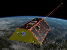 |
| Figure E-7 GRACE Satellites 5 |
5 NASA/Jet Propulsion Laboratory, https://www.jpl.nasa.gov/
The satellites would speed up or slow down relative to each as the pull of gravity changed, affecting the distance between them. Using GPS for positioning, even small gravity variations could be accurately located.
In 2017 with one satellite's batteries failing, the mission was officially terminated, outliving its project timeframe by 10 years. GRACE was so successful and the data so useful that GRACE-FO (Follow On) was launched in 2018 for another 5 year mission. NASA announced that GRACE-C (Continuity) is planned to launch in 2028.
5. Summary
The information in this chapter barely scratches the surface of gravity measurement. Gravity determination and geoid modeling are part of physical geodesy, a specialty within the geodetic science. Horizontal and vertical (and in the future, 3D) datums are dependent on the geoid. Because the Earth is not a static figure, gravity needs to be continually monitored to obtain the best geoid model representation. Better models are needed as technology continues to allow higher levels of measurement accuracy. What we couldn't discern 20 years ago has become routine today and will be considered crude tomorrow.