2. Parallel Plate Micrometer
a. What is it?
Also known as a optical micrometer, this is a device either attached to, or integrated with, the objective end of the telescope, Figure H-6. It consists of a parallel-sided glass plate which can be rotated in a vertical plane coinciding with the LoS.
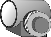 |
| (a) General design |
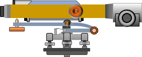 |
| (b) Attached to a tilting level |
| Figure H-6 Optical Micrometer |
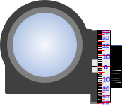
The plate is rotated using a graduated dial on the side or top of the device, Figure H-7. The gradations are subdivisions of the smallest interval on the rod.
 |
 |
| (a) End view | (b) Side ghost view |
| Figure H-7 Views |
|
An optical micrometer can be used with a Dumpy/Wye, tilting, or automatic level. It increases the rod reading resolution by dividing the smallest rod interval into tenths or hundredths. The micrometer must be matched to the rod units. For example, the micrometer in Figure H-7 is graduated from 0 to 100 in both directions. If set up for use with decimal feet, the micrometer's resolution is (1/100 x 0.01 ft) = 0.0001 ft.
b. How it works
The optical micrometer is based on displacement of a light ray passing through a flat glass plate. The displacement principle is discussed in I. Basic Principles Chapter H. General Optics 2. Refraction. This section describes its application for leveling.
When the LoS is perpendicular to the plate, it passes through unaffected., Figure H-8.
 |
| Figure H-8 LoS Perpendicular to Plate |
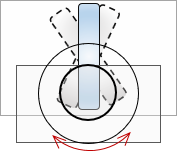
If the plate is rotated so the LoS strikes it at an angle, Figure H-9, the LoS is displaced vertically, emerging parallel with its original direction.
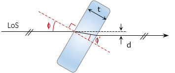 |
| Figure H-9 LoS At Angle To Plate |
The displacement amount is a function of the LoS angle, index of refraction of the glass, and glass thickness. The displacement, d, can be determined from Equations H-1 and H-2.
 |
Equation H-1 |
 |
Equation H-2 |
|
φ: Incidence angle |
|
At small angles, the sine and tangent are roughly equal. Using 1.0 for the atmospheric refraction index, combining Equations H-1 and H-2, and performing lots of rearranging results in Equation H-3 which simplifies computations a bit.
 |
Equation H-3 |
Values for n' and t are fixed based on the glass plate. The only unknown in Equation H-3 is the angle, φ. The dial uses geared connection to rotate the plate according to the tangent function of Equation H-3 solving the equation mechanically. LoS displacement is read directly off the micrometer dial.
c. How it is used.
(1) Rod and micrometer characteristics
The rod and micrometer must be matched. This procedural description uses a metric rod whose smallest interval is 0.01 m. Numbers on the right side of the rod are meters, on the left are 0.1 meters.
The micrometer is divided to ±100 so the finest reading is 1/100 x 0.01 m = 0.0001 m
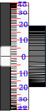
(2) The rod is sighted with the micrometer dial set to 0, Figure H-10.
Make note of the rod division immediately below the cross hair.
 |
 |
 |
| (a) Micrometer set to 0 | (b) Plate-LoS orientation | (c) Lower division: 1.65 m |
| Figure H-10 Initial Pointing |
||
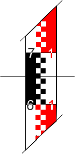
(3) Rotate the micrometer dial lowering the horizontal hair to coincide with the lower division, Figure H-11.
 |
 |
 |
| (a) Crosshair lowered to 1.65 | (b) Plate-LoS orientation | (c) Micrometer value: 46/100 |
| Figure H-11 Lower Coincident Reading |
||
The micrometer value is the amount the crosshair was above 1.65: (46/100) x 0.01 m = 0.0046 m
The reading is 1.65 plus the micrometer value: 1.65 + 0.0046 = 1.6546 m
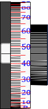
(4) Rotate the micrometer dial raising the horizontal hair to coincide with the upper division, Figure H-12.
 |
 |
 |
| (b) Crosshair raised to 1.66 | (b) Plate-LoS orientation | (c) Micrometer value: 56/100 |
| Figure H-12 Upper Coincident Reading |
||
The micrometer value is the amount the crosshair was below 1.66: (56/100) x 0.01 m = 0.0056 m
The reading is 1.66 minus the micrometer value: 1.65 - 0.0056 = 1.6544 m
(5) Final reading
The final reading is the average: (1.6546 + 1.6544) / 2 = 1.6545
d. 1/100 rod division? Too Good to be True?
Before getting too excited about the high degree of resolution, understand that the toughest part of using a parallel plate micrometer is lining up the horizontal crosshair with a rod division. Long sights and atmospheric distortions can make it extremely difficult. Parallax will also cause problems as will even the slightest gust of wind.
A geodetic level rod, which uses low thermal expansion material, is critical. A regular leveling rod does not have the thermal dimensional stability to support optical micrometer resolutions.
Other leveling error sources could potentially result in relative errors greater than the resolution.
Aligning the crosshair with rod marks, even under optimal conditions, is a best guess on the surveyor's part. The surveyor should back off and rematch the marks a few times to ensure consistency.
The final reading resolution should be limited to 1/10 the smallest rod interval:
- If the micrometer is resolution is 1/10, then use its reading as-is. : 1.785 m >> 1.785 m
- If resolution is 1/100, round final reading to 1/10: 2.0136 m >> 2.014 m