1. Tilting Level
a. Definition
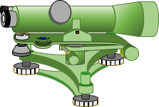
A tilting level is a modified Dumpy level. Its name comes from the ability to slightly tilt its telescope. A Dumpy level's line of sight is fixed with respect to its vertical axis. The tilting level's telescope, however, has a horizontal pivot located at the vertical axis, A in Figure H-1. Toward the eyepiece end is the tilt knob, B, Figure H-1, located under the telescope. When rotated. it raises or lowers the telescope end, tilting the LoS. A circular bubble is used to roughly level the instrument and a separate bubble vial to level the telescope. Before a backsight or foresight reading, the surveyor uses the tilt knob to level the line of sight.
|
|
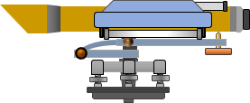 |
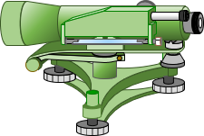
| Figure H-1 Tilting Level, Side Views |
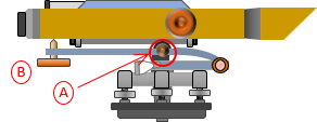
The bubble vial is generally enclosed to protect it from the elements and mishandling. It is viewed through a window or an auxiliary eyepiece, C in Figure H-2. An adjustable mirror, D in Figure H-2, is rotated to reflect light through the bubble.
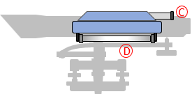 |
| Figure H-2 Bubble |
b. Let's Split!
Instead of a bubble tube with gradations, a split view bubble is used. Looking through the view window or auxiliary eyepiece, the surveyor sees both ends of the bubble combined onto a single image, Figure H-3(a). Rotating the tilt knob will cause the two bubble halves to move; the bubble is centered when both ends coincide, Figure H-3(b).
 |
 |
| (a) Off center | (b) Centered |
| Figure H-3 Split Bubble |
|
A split view bubble is easier to center than using a graduated bubble vial.
c. Leveling screws and optics
Early tilting levels were four-screw instruments. They had long telescopes, being derived from a Dumpy level, and most presented the surveyor with an inverted image of the rod.
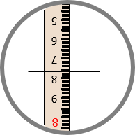 |
| Figure H-4 Inverted Image |
Why inverted? Chiefly due to optics quality avialable for earlier instruments. A single bi-convex lens inverts the image of the object on which it is focused. It also introduces optical errors (refer to Chapter H. General Optics Section 7). To see an upright image and correct some errors, another lens must be added. The more lenses, the greater the effect of optical defects. Minimizing optical elements reduced optical errors but at the cost of an inverted image.
As optics improved, later tilting levels had shorter telescopes with upright images and used a three-screw leveling head, Figure H-5.
 |
 |
| Figure H-5 Three-Screw Tilting Level, Side Views |
|
d. Type of differential leveling
A tilting level can be used for simple differential or geodetic-quality leveling. The procedures for either can be:
- Single reading BS and FS
- Three-wire BS and FS
- Optical micrometer (next section)
While a relatively flexible instrument, it has been largely supplanted by mechanical and electronic automatic levels.