Chapter H. Geodetic Leveling Equipment
Geodetic leveling is based on differential leveling, with some differences in the equipment and procedural variations. Because geodetic leveling is used to establish elevation control networks, error minimization is particularly critical. Equipment and procedures reflect this. This chapter briefly describes some typical equipment historically used for geodetic surveying.
For a complete description of current geodetic leveling equipment and procedures, refer to NOAA Manual NOS NGS 3 Geodetic Leveling available in the publications area at the NGS website.
1. Tilting Level
a. Definition
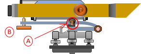
A tilting level is a modified Dumpy level. Its name comes from the ability to slightly tilt its telescope. A Dumpy level's line of sight is fixed with respect to its vertical axis. The tilting level's telescope, however, has a horizontal pivot located at the vertical axis, A in Figure H-1. Toward the eyepiece end is the tilt knob, B, Figure H-1, located under the telescope. When rotated. it raises or lowers the telescope end, tilting the LoS. A circular bubble is used to roughly level the instrument and a separate bubble vial to level the telescope. Before a backsight or foresight reading, the surveyor uses the tilt knob to level the line of sight.
|
|
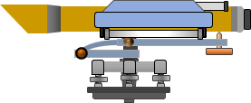 |
| Figure H-1 Tilting Level, Side Views |
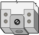
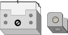
The bubble vial is generally enclosed to protect it from the elements and mishandling. It is viewed through a window or an auxiliary eyepiece, C in Figure H-2. An adjustable mirror, D in Figure H-2, is rotated to reflect light through the bubble.
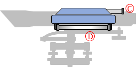 |
| Figure H-2 Bubble |
b. Let's Split!
Instead of a bubble tube with gradations, a split view bubble is used. Looking through the view window or auxiliary eyepiece, the surveyor sees both ends of the bubble combined onto a single image, Figure H-3(a). Rotating the tilt knob will cause the two bubble halves to move; the bubble is centered when both ends coincide, Figure H-3(b).
 |
 |
| (a) Off center | (b) Centered |
| Figure H-3 Split Bubble |
|
A split view bubble is easier to center than using a graduated bubble vial.
c. Leveling screws and optics
Early tilting levels were four-screw instruments. They had long telescopes, being derived from a Dumpy level, and most presented the surveyor with an inverted image of the rod.
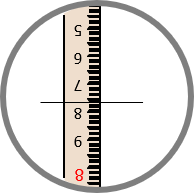 |
| Figure H-4 Inverted Image |
Why inverted? Chiefly due to optics quality avialable for earlier instruments. A single bi-convex lens inverts the image of the object on which it is focused. It also introduces optical errors (refer to Chapter H. General Optics Section 7). To see an upright image and correct some errors, another lens must be added. The more lenses, the greater the effect of optical defects. Minimizing optical elements reduced optical errors but at the cost of an inverted image.
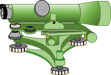
As optics improved, later tilting levels had shorter telescopes with upright images and used a three-screw leveling head, Figure H-5.
 |
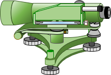 |
| Figure H-5 Three-Screw Tilting Level, Side Views |
|
d. Type of differential leveling
A tilting level can be used for simple differential or geodetic-quality leveling. The procedures for either can be:
- Single reading BS and FS
- Three-wire BS and FS
- Optical micrometer (next section)
While a relatively flexible instrument, it has been largely supplanted by mechanical and electronic automatic levels.
2. Parallel Plate Micrometer
a. What is it?
Also known as a optical micrometer, this is a device either attached to, or integrated with, the objective end of the telescope, Figure H-6. It consists of a parallel-sided glass plate which can be rotated in a vertical plane coinciding with the LoS.
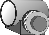 |
| (a) General design |
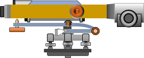 |
| (b) Attached to a tilting level |
| Figure H-6 Optical Micrometer |
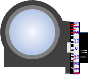
The plate is rotated using a graduated dial on the side or top of the device, Figure H-7. The gradations are subdivisions of the smallest interval on the rod.
 |
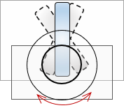 |
| (a) End view | (b) Side ghost view |
| Figure H-7 Views |
|
An optical micrometer can be used with a Dumpy/Wye, tilting, or automatic level. It increases the rod reading resolution by dividing the smallest rod interval into tenths or hundredths. The micrometer must be matched to the rod units. For example, the micrometer in Figure H-7 is graduated from 0 to 100 in both directions. If set up for use with decimal feet, the micrometer's resolution is (1/100 x 0.01 ft) = 0.0001 ft.
b. How it works
The optical micrometer is based on displacement of a light ray passing through a flat glass plate. The displacement principle is discussed in I. Basic Principles Chapter H. General Optics 2. Refraction. This section describes its application for leveling.
When the LoS is perpendicular to the plate, it passes through unaffected., Figure H-8.
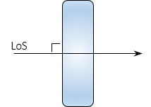 |
| Figure H-8 LoS Perpendicular to Plate |
If the plate is rotated so the LoS strikes it at an angle, Figure H-9, the LoS is displaced vertically, emerging parallel with its original direction.
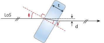 |
| Figure H-9 LoS At Angle To Plate |
The displacement amount is a function of the LoS angle, index of refraction of the glass, and glass thickness. The displacement, d, can be determined from Equations H-1 and H-2.
 |
Equation H-1 |
 |
Equation H-2 |
|
φ: Incidence angle |
|
At small angles, the sine and tangent are roughly equal. Using 1.0 for the atmospheric refraction index, combining Equations H-1 and H-2, and performing lots of rearranging results in Equation H-3 which simplifies computations a bit.
 |
Equation H-3 |
Values for n' and t are fixed based on the glass plate. The only unknown in Equation H-3 is the angle, φ. The dial uses geared connection to rotate the plate according to the tangent function of Equation H-3 solving the equation mechanically. LoS displacement is read directly off the micrometer dial.
c. How it is used.
(1) Rod and micrometer characteristics
The rod and micrometer must be matched. This procedural description uses a metric rod whose smallest interval is 0.01 m. Numbers on the right side of the rod are meters, on the left are 0.1 meters.
The micrometer is divided to ±100 so the finest reading is 1/100 x 0.01 m = 0.0001 m
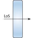
(2) The rod is sighted with the micrometer dial set to 0, Figure H-10.
Make note of the rod division immediately below the cross hair.
 |
 |
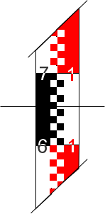 |
| (a) Micrometer set to 0 | (b) Plate-LoS orientation | (c) Lower division: 1.65 m |
| Figure H-10 Initial Pointing |
||
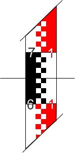
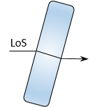
(3) Rotate the micrometer dial lowering the horizontal hair to coincide with the lower division, Figure H-11.
 |
 |
 |
| (a) Crosshair lowered to 1.65 | (b) Plate-LoS orientation | (c) Micrometer value: 46/100 |
| Figure H-11 Lower Coincident Reading |
||
The micrometer value is the amount the crosshair was above 1.65: (46/100) x 0.01 m = 0.0046 m
The reading is 1.65 plus the micrometer value: 1.65 + 0.0046 = 1.6546 m
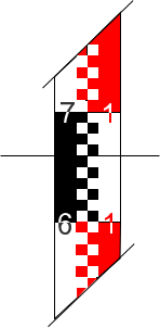
(4) Rotate the micrometer dial raising the horizontal hair to coincide with the upper division, Figure H-12.
 |
 |
 |
| (b) Crosshair raised to 1.66 | (b) Plate-LoS orientation | (c) Micrometer value: 56/100 |
| Figure H-12 Upper Coincident Reading |
||
The micrometer value is the amount the crosshair was below 1.66: (56/100) x 0.01 m = 0.0056 m
The reading is 1.66 minus the micrometer value: 1.65 - 0.0056 = 1.6544 m
(5) Final reading
The final reading is the average: (1.6546 + 1.6544) / 2 = 1.6545
d. 1/100 rod division? Too Good to be True?
Before getting too excited about the high degree of resolution, understand that the toughest part of using a parallel plate micrometer is lining up the horizontal crosshair with a rod division. Long sights and atmospheric distortions can make it extremely difficult. Parallax will also cause problems as will even the slightest gust of wind.
A geodetic level rod, which uses low thermal expansion material, is critical. A regular leveling rod does not have the thermal dimensional stability to support optical micrometer resolutions.
Other leveling error sources could potentially result in relative errors greater than the resolution.
Aligning the crosshair with rod marks, even under optimal conditions, is a best guess on the surveyor's part. The surveyor should back off and rematch the marks a few times to ensure consistency.
The final reading resolution should be limited to 1/10 the smallest rod interval:
- If the micrometer is resolution is 1/10, then use its reading as-is. : 1.785 m >> 1.785 m
- If resolution is 1/100, round final reading to 1/10: 2.0136 m >> 2.014 m
3. Rod
The level rod is as important as the level instrument in a geodetic survey.Indistinct or irregularly spaced markings can defeat the purpose of using a geodetic instrument.
General characteristics of a geodetic rod are:
a. One piece
No joints which can create division spacing error. Length of a single piece rigid rod can be limited by transportation issues. If used for three-wire leveling, this also limits maximum BS and FS distances.
b. Low expansion
The structural material of the rod can vary, A in Figure H-13, but the linear divisions are on a low thermal expansion material, B in Figure H-13. Invar (also used in precise taping) is traditionally used because of its stability
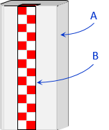 |
| Figure H-13 Rod Composition |
c. Base
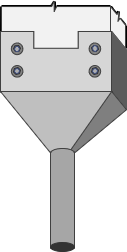
Because elevations are determined to a greater resolution than in regular leveling, it is essential that the numeric origin of the rod sit on the point observed. That is why benchmark monuments and turning points generally have domed tops - so they have a distinct high point on which to place the rod. Most geodetic level rods have a base that is small or flat with a guide, Figure H-14.
 |
|
| (a) Small | (b) Flat and removable guide |
| Figure H-14 Rod Bases |
|
The rod reading at the contact point for each is 0, with readings increasing upward.
The design of the base in Figure H-14(a) forces the minimum reading to be at least the height of the base above the ground. This is to ensure the LoS is above the boundary layer that is subject to residual heat waves not visible to the naked eye. The FGCS geodetic leveling specifications require the LoS be no lower than 0.5 m on the rod.
The rod base in Figure H-14(b) is flat but has a detachable guide to facilitate setting up on a dome point benchmark or turning point without sliding off.
d. Distinct markings
A geodetic rod is wider than its basic leveling counterpart to have room for distinct makings and numbering. Two metric rod examples are shown in Figure H-15.
 |
 |
| (a) Example 1 | (b) Example 2 |
| Figure H-15 Metric Rods |
|
The rod design in Figure H-15(a) is used for three-wire or micrometer leveling
- Numbers on the right are full meters; on the left are 0.1 m
- Alternating colors are used every 0.1 m
- Rod divisions are 0.01 m
The rod design in Figure H-15(b) is used with an inverted image instrument.
- The rod image appears upright when viewed through the instrument
- Numbers are cm
- Rod division interval is 1 cm
- Dual scale rod; scales are offset a constant amount, 279.5 cm in this example
- Both scales are read as a check
These are just two examples of many different rod designs. While there are rods with English linear units, most geodetic leveling is done in the metric system.
For formal geodetic leveling the rod must be calibrated.
e. Bipod
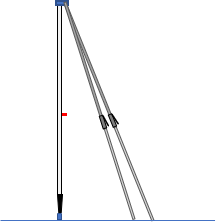
The rod must be held vertically long enough for the instrument person to take and verify his/her readings. This can take a bit of time when three-wire leveling or using an optical micrometer. A set of bipod legs, with quick release locks, are attached to the back or top of the rod, Figure H-16.
 |
| Figure H-16 Bipod |
These, with the circular bubble on the rod, make set up quick and stable.
4. Turning Points
Any point used to hold an elevation, even temporarily, should have a distinct top and be stable. Most formal benchmarks are either domed disks set concrete or spherical topped invar bars driven to refusal. When running a geodetic circuit to establish local networks, turning points are often needed as intermediate temporary elevations. To maintain circuit integrity, a physical object used as a turning point must also have a distinct top and be stable. Flat surfaces such as sidewalks, pavements, etc, should not be used because they may have a slight slope or the rod base may not sit flat.
Chapter B. Differential Leveling Section 2 Equipment identified two objects, steel pins and turtles, typically used for turning points. These same objects are used for geodetic leveling although the pin is usually stainless steel and has a driving cap. With the cap on, Figure H-17(a), the pin is driven into the ground. Once the pin is solid, the cap is removed revealing a spherically topped stub used as the actual turning point, Figure H-17(b).
 |
 |
| (a) Driving | (b) Surveying |
| Figure H-17 Pin |
|
The cap, usually attached with a chain, protects the stub during hammering.
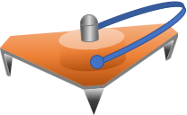
A turtle, Figure H-18, is either a circular or triangular plate with three short legs and a centrally located spherical top stub.
 |
| Figure H-18 Turtle |
The plate is heavy so when dropped it drives the legs into the ground. On hard surfaces such as pavement or sidewalks, dropping the turtle will still generally cause its legs to bite into the surface. With only three legs, it will not wobble on a hard surface. The turtle can be used on sloped surfaces since the top of the stud is spherical and will have a distinct top at various orientations.
