1. Instrumental
Many instrumental maladjustments can be compensated by procedure or by adjusting the equipment. This chapter describes procedural or mathematical compensation, equipment adjustment is covered in Topic XV Equipment Checks and Adjustments.
a. Sticking compensator
(1) Description
The compensator maintains a horizontal line of sight when the instrument is slightly out of level. A sticking compensator will not react correctly if the instrument's level condition is disturbed.
(2) Check
The process is described in Figure D-1.
|
Set up and level the instrument. Clear parallax. |
 |
| Sight a level rod and note the reading. |  |
| While sighting the rod, use a finger to firmly and gently press down on the forward end of the telescope. This will deflect the line of sight changing the reading. |  |
| While holding the telescope depressed, the crosshairs should return to the initial reading. This is the compensator reacting as it should. |  |
| Remove pressure from the telescope front; the line of sight will go up and then... |  |
|
... should return to the initial rod reading. |
|
|
Figure D-1 |
|
Another way to check the compensator is to take a reading with the circular bubble centered, turn one of the leveling screws making the instrument slightly out of level, and check the reading again. If the second reading matches the first then the compensator is operating correctly. This must be done with care as turning a level screw too much can change the instrument’s elevation which can affect the second rod reading.
(3) Behavior
A level with a sticky or inoperable compensator cannot be reliably used. Its behavior is random and is not apparent when reading a rod.
(4) Compensation
If the compensator does not respond correctly, it should be sent in for repair. The internal mechanism is delicate and sealed from dust and should only be adjusted by a qualified service technician.
b. Horizontal crosshair
(1) Description
On an adjusted level, the horizontal crosshair is truly horizontal when the instrument is correctly set up. This allows accurate rod reading using any part of the crosshair.
(2) Check
Follow the process shown in Figure D-2
|
Set up and level the instrument. Clear parallax. |
|
| Sight a rod with one end of the horizontal crosshair and note the rod reading. | 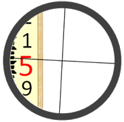 |
|
While sighting through the telescope, use the slow motion to horizontally scan across the rod. If the reading doesn't change. the horizontal crosshair is in adjustment. |
 |
|
Figure D-2 |
|
(3) Behavior
As long as the adjusting screws are not loose, the crosshairs will maintain their orientation resulting in systematic behavior.
(4) Compensation
(a) Adjustment - See Topic XV Chapter C Automatic Level.
(b) Procedural - Use the crosshairs' intersection for all rod readings, Figure D-3.
|
|
| Figure D-3 Horizontal Hair Compensation |
c. Collimation
(1) Description
On an adjusted instrument which is correctly set up, the Line of Sight (LoS) should be horizontal and perpendicular to the Vertical Axis (VA).
(2) Check
The check for a horizontal LoS is quite involved and discussed in Topic XV Chapter C Automatic Level. The check is not usually performed on a daily basis, however it can be compensated proceduraly.
(3) Behavior
A non-horizontal LoS means the instrument has a collimation error. A LoS that is inclined or depressed from horizontal, Figure D-4, introduces a rod reading error.
 |
| Figure D-4 Collimation Error |
Collimation error is caused by the vertical position of the crosshairs: if they are too low then the LoS is inclined; if they are too high, the LoS is depressed.
The amount of reading error is a function of distance, Figure D-5. The error increases linearly as distance increases, e.g., the error at 200 ft is twice that at 100 ft. Collimation error is systematic.
 |
| Figure D-5 Collimation Error Behavior |
(4) Compensation
(a) Adjustment - the instrument can be adjusted by performing a collimation check, explained in Topic XV Chapter C Automatic Level.
(b) Mathematical - A byproduct of the collimation check is the actual collimation error expressed as an angle or a vertical-to-horizontal ratio. This can be applied to rod readings as long as the sight lengths are known. A numeric example is included in Topic XV Chapter C Automatic Level.
(c) Procedural - For most leveling projects, collimation error can be removed by balancing BS and FS distances, that is, making them equal.
 |
| Figure D-6 Collimation Error Compensation |
If the BS and FS distances are equal, Figure D-6, then the reading error in both will be the same: eBS=eFS. Because ElevB = ElevA + BS - FS, the BS error (eBS) is added and the FS (eFS) error is subtracted so the collimation error cancels. That means that the elevation of B is correct with respect to A if the BS and FS distances are equal. However, the EI is incorrect since it is subject only to the BS error. That's why in differential leveling we have one BS and one FS per setup and make sure their distances are approximately equal.
How close must the BS and FS distances be? It depends on the accuracy level of the survey. Table D-1 shows the maximum allowable BS and FS distance difference (as well as maximum distance) for formal First, Second, and Third Order geodetic leveling.
| Table D-1 |
 |
| units are meters per setup is for each instrument setup per section is cumulative difference for each closed network |
| From Standards and Specifications for Geodetic Control Networks, FGCS, 1984; Section 3.5 Geodetic Leveling. |
Considering that Third Order allows a 10 meter (~33 ft) differential, keeping distances balanced within several paces for local projects should be sufficient. Yes, pacing is an acceptable way to balance distances.
Balancing BS and FS distances works without having to determine the collimation error. If present, the error cancels.
d. Rod bubble
(1) Description
A rod bubble is used to keep the rod vertical for readings. If the rod bubble is off, then the rod will not be vertical and reading errors will be introduced.
(2) Check
Because a rod bubble lives a hard life, it should be checked at the beginning of each leveling day. A rod bubble can be checked using a prism pole having an adjusted bubble. Other methods are explained in Topic XV Chapter B The Grunt Stuff.
(3) Behavior
Bubble maladjustment is a systematic error. Regardless how it is held against a rod, it will cause the rod to be off vertical the same amount. If the rod is off vertical, readings will be too high.
(4) Compensation
(a) Adjustment - Follow the procedure in Topic XV Chapter B The Grunt Stuff.
(b) Mathematical - Even though the error is systematic, a mathematical correction cannot be computed unless the amount of bubble maladjustment is known.
(b) A maladjusted bubble should not be used, neither should a bubble whose adjustment can't be verified. Instead of using the bubble, slowly wave (rock) the rod toward and away from the instrument operator, Figure D-7.
 |
| Figure D-7 Waving the Rod |
The instrument person will see the readings increase and decrease as the rod is rocked. The lowest reading occurs when the rod is vertical.
e. Waving (rocking) a rod
(1) Description
If the rod is slowly waved back and forth, the instrument person will see the reading rise and fall; the rod is vertical when the reading is lowest.
(2) Check
The lowest reading can be verified by using an adjusted bubble.
(3) Behavior
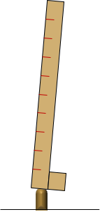
An error could be introduced, however, if the rod is sitting on a hard flat surface. On older Philadelphia rods which have sliding sections, the bottom of the rod is deep enough to support the upper section when collapsed. This gives the rod a larger footprint than a telescoping rod. When the rod is rock backward, the pivot point is at the back of this footprint and it actually raises the rod a little.
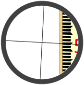
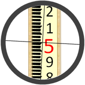
In Figure D-8, each division line represents a tenth of a foot. When the rod is vertical, it reads 1.00 ft. When tipped back approximately 5 degrees, the reading is below 1.00 ft. The lowest reading, in this situation, is not the correct one. Here it appears to introduce an error of about 0.014 ft in the first foot on the rod. Readings higher up on this tipped rod will have slightly increasing error. Tipping the rod forward a like amount will have less error.
 |
| Figure D-8 Waving Rod Error |
Even shallower rods will experience a certain amount of "lift" when rocked. Because it results from a rod's physical dimensions, it behaves systematically.
When three-wire levelling, the rod should not be rocked at all because the it only works for the center crosshair, Figure D-9
 |
| Figure D-9 Three-wire Levelling |
(4) Compensation
Use an adjusted rod bubble, especially if running three-wire leveling. This is the best procedural solution.
A turning pin or turtle with a rounded tip prevents rod lift, Figure D-10, but only on intermediate points. Rocking the rod on non-round top points can still cause errors.
 |
| Figure D-10 |