Page 2 of 5
2. Ground Distance to Grid
a. Ground to Ellipsoid
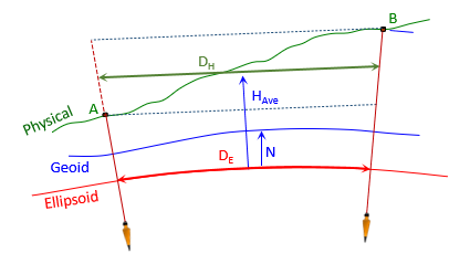 |
| Figure L-2 Ground to Geodetic |
We computed geodetic distances in Chapter K - those can be converted to meters to use here.
However, we'll do the computations from scratch using Equation H-2 to.
Jerry's -33.902 meter geoid height will be used as a project average.
Equation H-2
(1) Geodetic distance Jerry-A1

(2) Geodetic distance Jerry-B7

b. Ellipsoid to Grid
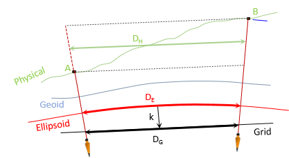 |
| Figure L-3 Geodetic to Grid |
We'll use and compare the same reductions for UTM as we did for SPC. Table L-2 shows the grid scale at each point and how they were obtained.
| Table L-2 Grid Scales |
||
| Point |
Scale |
Source |
| A1 | 1.00020 6404 | software |
| Jerry-A1 midpoint | 1.00020 9086 | Equation H-4 |
| Jerry | 1.00021 177 | datasheet |
| Jerry-B7 midpoint | 1.00021 5856 | Equation H-4 |
| B7 | 1.00020 8953 | software |
Jerry's CF from the datasheet is 1.00016 082.
Because the process is similar to SPC grid reduction, computations are not shown but results are summarized in Tables L-3 and L-4.
DE x k k
Grid Dist, m
Diff, m
Wtd Ave k 1.00020 9086 1305.3993
- -
Average k 1.00020 9087
1305.3993
0.0000
Jerry's k 1.00021 177
1305.4028
+0.0035
Combined Factor DH x CF 1.00016 082
1305.4000
+0.0007
Unlike SPC reduction, using Jerry's scale as a project average resulted in the largest differences. Average line scale worked well. Jerry's CF reduction had small (inconsequential?) differences. Using CF reduction could be sufficient if the elevations of points A1 and B7 represent the range across the project.
DE x k k
Grid Dist, m
Diff, m
Wtd Ave k 1.00021 4025
1568.8175
- -
Average k 1.00021 0362
1568.8175
0.0000
Jerry's k 1.00021 177
1568.8111
-0.0064
Combined Factor DH x CF 1.00016 082
1568.8173
-0.0002