7. Errors Sources and Behavior
Because an EDM is integrated into a TSI, many of TSI-related errors also apply to EDM use. This section will only address errors which affect distance determination by EDM.
a. Instrumental
(1) Reflector pole bubble
(a) Description
An error in a reflector pole's circular bubble will cause the reflector to be shifted off the ground point affecting the measured distance.
(b) Behavior
Systematic. Horizontal distance can be affected; vertical distance is not significantly affected.
(c) Compensation
Procedure: Us an adjusted bubble to level the reflector pole.
Mechanical: The bubble should be checked and adjusted as described in XV. Equipment Checks and Adjustments Chapter B. The Basic Stuff.
(2) Tribrach circular bubble
(a) Description
The bubble on a tribrach is used to level the reflector. If the level is off, it has minimal effect on distance measurement because the reflector will still return the signal.
If the tribrach has an optical plummet, using it with a maladjusted bubble cause the reflector to be shifted off the ground point
(b) Behavior
Systematic. Horizontal distance can be affected; vertical distance is not significantly affected.
(c) Compensation:
Procedure: Use a plumb bob instead of the optical plummet to set up over the ground point. As long as the reflector is approximately level, it will return the EM signal.
Mechanical: Adjust the tribrach's bubble as described in XV. Equipment Checks and Adjustments Chapter B. The Basic Stuff.
(3) Tribrach: optical plummet
(a) Description
The optical plummet on a reflector tribrach is used to orient the reflector vertically over its ground mark. Any maladjustment will shift the reflector's position.
(b) Behavior
Systematic. Horizontal distance can be affected; vertical distance is not significantly affected.
(c) Compensation
Procedure: Use a plumb bob instead of the optical plummet to set up over the ground point.
Mechanical: Adjust the tribrach's optical plummet as described in XV. Equipment Checks and Adjustments Chapter B. The Basic Stuff.
(3) Manufacturer's Stated Accuracy (MSA)
(a) Description
Each EDM/TSI has an inherent random uncertainty in distance measurement. This is the Manufacturer's Stated Accuracy (MSA) and is specified in the instrument manual. It is expressed as a two part uncertainty: (1) a constant, and, (2) a proportion based on distance. An example is an MSA of ±(2mm + 3ppm). Every distance measured with this TSI would have an expected error of:
Constant = ±2 mm x (39.37 in/1 m) x (1 m/1000 mm) x (1 ft/12 in) = ±0.006 ft
The proportional error will increases as do distances.
In a 100.00 ft distance, the expected proportional error is: 100.00 ft x (±3/1,000,000) = ±0.0003 ft
For 1000.00 ft: 1000.00 ft x (±3/1,000,000) = ±0.003 ft
The two errors are not independent of each other: a single direct measurement is affected by both errors.
(b) Behavior
Random.
(c) Compensation
Use an EDM/TSI with an MSA that supports the required accuracy of the measurement. Repeat the measurement multiple times and use the average.
(4) Combined constant
(a) Description
The raw slope distance is between the EM origin and the optical center of the reflector. Neither may be located vertically above the respective ground point.
At the EDM/TSI the EM signal is generated internally, Figure F-16, then optically made to coincide with the instrument's line of sight. The offset is CI.
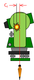 |
| Figure F-16 EM Center |
At the reflector, the EM path slows as it enters the glass and is reflected internally. If the effective distance were plotted as a straight line, the apparent optical center of the reflector would be slightly behind it, Figure F-17. The distance between the optical center and the vertical line through the ground point is CP.
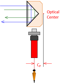 |
| Figure F-17 Reflector Optical Center |
Most holders allow mounting the reflector on the front or back, Figure F-18.
|
|
| Figure F-18 Mount Offsets |
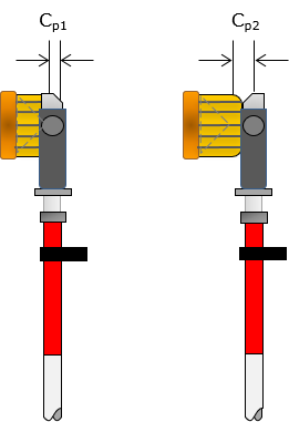
Depending on the side, the reflector is either closer to or further from the EDM/TSI which affects the optical center offset. Contemporary holders generally have the offset value printed on the respective side.
The corrected distance is the sum of the slope distance, EDM/TSI offset, and reflector offset, Figure F-19 and Equation F-4.
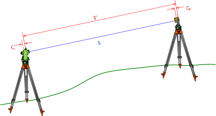 |
| Figure F-19 Measurement Constant |
 |
Equation F-4 |
|
S: corrected slope distance |
|
(b) Behavior
Systematic
(c) Compensation
Procedure: The combined constant should be entered in EDM/TSI prior to measurement. The procedure for determining the combined constant is covered in XV. Equipment Checks and Adjustments Chapter D. Electronic Distance Measurement.
Mathematical: The reflector constant, adjusted for the zenith/vertical angle, should be added/subtracted from the distance. Prior to applying the correction, check if the EDM/TSI has been set with a different constant. If so, adjust the correction accordingly.
(5) Reflector height
(a) Description
For as simple an instrument as is the reflector pole, it can lead to some problems. We have already discussed the pole's bubble; what about its height?
Reflector pole height does not affect horizontal distance determination. Remember that the TSI uses a zenith angle with the slope distance to compute the horizontal distance. Reflector height doesn't matter since raising or lowering it will change both zenith angle and slope distance but still result in the same horizontal distance.
Reflector height can come into play in topographic surveys where elevations are determined trigonometrically using instrument and reflector heights. It behaves systematically. The error and compensation are discussed in IV. Elevations Chapter F. Trigonometric Leveling.
b. Natural
(1) Atmospheric conditions
(a) Description
Electro-optical EM signals are affected by atmospheric pressure and temperature. TSIs are generally standardized at a specific temperature and pressure. When measurement conditions deviate from either then a proportional correction must be applied. This is normally done by the TSI after the operator provides it some necessary information (temperature and pressure or the actual correction factor).
(b) Behavior
Systematic.
(c) Compensation
Procedure: The correction or temperature and pressure are entered in the instrument.
Mathematical: Compute and apply the corrections manually after the fact.
Typical equations for the atmospheric correction are:
| English | ||
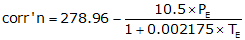 |
Equation F-5 | |
| PE: Pressure, in Hg TE: Temperature; ºF |
||
| Metric | ||
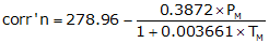 |
Equation F-6 | |
|
PM: Pressure, mm Hg |
||
Different manufacturers may use slightly different standardization conditions so refer to the user manual for the correction equations for a partucular instrument.
Use Equation F-7 to correct the raw distance.
| D = D'x(1+corr'n) | Equation F-7 |
|
D: Corrected distance |
|
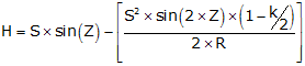
(2) Curvature and refraction
(a) Description
The effects of curvature and refraction on the line of sight are described in II. Errors Chapter E. Systematic Errors. The EDM's EM wave is also bent, affecting horizontal and vertical distances both. Figure F-20 shows the curvature and refraction geometry for distance measurement.
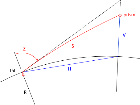 |
| Figure F-20 Slope Reduction, Z<90° |
Red line, S, is the slope distance coincident with the LoS.
The black line is tangent to S at the instrument.
Zenith angle, Z, is measured to the black tangent.
Blue line, H, is the "horizontal" distance.
Blue line, V, is the vertical distance.
In plane surveying, horizontal distance is always shorter than the corresponding slope distance. This isn't the case in geodetic surveying. When the zenith angle exceeds 90°, slope distance is shorter than horizontal, Figure F-21.
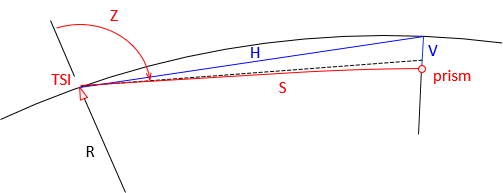 |
| Figure F-21 Slope Reduction, Z Near 90° |
This is demonstrated in the Example Computations section.
(b) Behavior
Systematic
(c) Compensation
Procedure: Modern instruments have the ability to apply refraction and curvature corrections as measurements are made. Data collection software also provide a correction option as does some desktop surveying software. Care must be exercised so that the correction is not applied multiple times. The safest approach is to turn on the correction in the instrument and not in the data collection or desktop software.
Mathematical: Most instrument manuals will describe the algorithms used ti account for curvature and refraction. Equations F-8 and F-9 are examples from one instrument's manual.
|
|
Equation F-8 | |
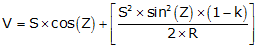 |
Equation F-9 | |
| H: Horizontal distance V: Vertical distance S: Slope distance Z: Zenith angle k: refraction constant; low elev: 0.14, high elev: 0.07 R: Earth radius |
||
If the corrections are not applied in the instrument, they can accounted for later.
(3) Atmospheric anomalies
(a) Description
The atmospheric correction and refraction are based on an assumption that the atmosphere is either uniform or changing uniformly along the signal path. This is not always the case. Consider the atmosphere immediately above an asphalt surface on a sunny day - the heat emitted by the surface causes a local atmospheric anomaly which affects the signal path. Almost any surface will have a boundary layer of atmospheric disturbance if it has been subject to sunlight.
(b) Behavior
Random.
(c) Compensation
The effect of atmospheric anomolies can only be minimized or eliminated by not measuring through them. This isn't always practical. For example many Public Land Survey (PLS) corners are located in roads. Not only might the surveyor have to deal with an anomaly at a PLS corner, he may be measuring along the pavement to an adjacent corner half a mile away.
Strategies can include measuring on a cloudy day, late at night, or early morning. Depending on the surface, increasing the TSI and/or reflector height may raise the signal sufficiently above the boundary layer.
a. Personal
(1) Equipment centering
(a) Description
This involves how accurately the operator can center the instrument or tribrach vertically over the ground mark. If using a hand held reflector pole, how carefully the rodperson holds the bubble centered.
(b) Behavior
Random.
(c) Compensation
Practice, practice, practice.
(2) Atmospheric conditions determination
(a) Description
Temperature and barometric pressure must be obtained for the time of measurement.
(b) Behavior
Systematic.
(c) Compensation
If conditions cannot be ascertained in the field, the operator should record the existing settings in the instrument. Conditions at measurement time can be determined from the internet or local radio/TV station later. The measurements can then be "uncorrected" for the recorded field conditions and "re-corrected" using the appropriate data.