d. Line of Sight
(1) Description
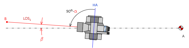
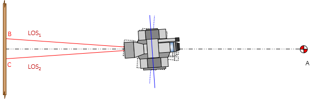
The LOS should be perpendicular to the HA to allow straight lines to be prolonged by rotating the telescope in a vertical plane.
(2) Check
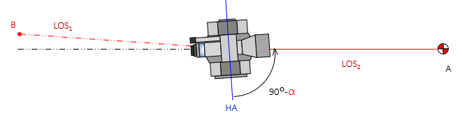
The check is performed by Double Centering. To minimize pointing errors, use sights at least 200 feet long. The instrument is set up and leveled, then a sight is taken on a distinct target or point, Figure G-21.
 |
| Figure G-21 Step 1 |
Angle α is error in the LOS-HA perpendicular condition.
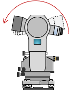
The telescope is rotated about the HA, Figure G-22(a), to set point, B, opposite the instrument from point A, Figure G-22(b).
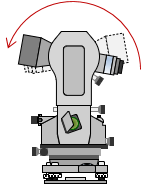 |
| (a) Reverse Telescope |
 |
| (b) Set Foresight Point |
| Figure G-22 Step 2 |
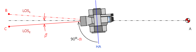
If in adjustment, the instrument and points A and B will be colinear. Otherwise the angle β is twice the error, angle α.
The instrument is rotated around the VA, Figure G-23(a), and point A is sighted again, Figure G-23(b).
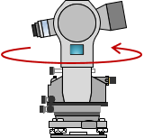 |
| (a) Rotate Instrument |
 |
| (b) Backsight |
| Figure G-23 Step 3 |
The telescope is rotated about the HA, Figure G-24(a), to set another point C opposite the instrument from point A, Figure G-24(b).
 |
| (a) Reverse Telescope |
 |
| (b) Set Foresight Point |
| Figure G-24 Step 4 |
If in adjustment, points B and C will coincide.
If the LOS is not perpendicular to the HA, the plane in which a vertical angle is measured is offset from the instrument's VA. The further away the point, the greater the offset. Think of the LOS as tracing out a cone as the telescope is rotated, Figure G-25.
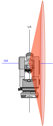 |
| Figure G-25 Maladjustment Effect |
The cone is centered on the instrument and its axis coincides with the instrument's HA.
(3) Compensation
(a) Procedure
Set the correct colinear point, D, halfway between points B and C, Figure G-26.
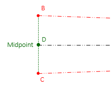 |
| Figure G-26 Procedural Compensation |
(b) Adjustment
Because the instrument was reversed twice, the distance between points C and D is four times the error. To correct the condition, use the crosshair adjusting screws. They are located immediately forward of the eyepiece, usually under a protective cover. Use the horizontal screw(s) to move the crosshairs 1/4 the distance from point C in the direction of point B, Figure G-27.
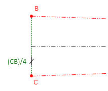 |
| Figure G-27 Adjustment |
Note
A level rod laid on its side approximately perpendicular to the line, Figure G-28, can be used if the instrument will be adjusted.
Figure G-28
Using a Level Rod
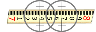
Instead of setting points B and C, readings are taken on the rod, Figure G-29.
Figure G-29
Rod SightsSight distances to points B and C can be shorter since the level rod will be read. This is both easier and more accurate than trying to mark two points. The distance CB can be quickly computed and the adjustment made.