c. Optical Plummet
(1) Description
The optical plummet takes the place of a plumb bob for instrument set up over a ground point. When the instrument is level, the OPA is both horizontal and vertical. The vertical component should coincident with the instrument's VA.
There are two ways to check and compensate for a maladjusted optical plummet depending whether it rotates with the instrument or not. This chapter covers rotating plummets because those are common on theodolites and TSIs. The other type is discussed in Chapter B. The Basic Stuff.
(2) Check
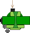
Precisely level the instrument and use the optical plummet to accurately set up over a ground point, Figure G-14.
 |
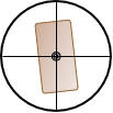 |
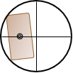
| (a) Top View | (b) View Through Plummet |
| Figure G-14 Centered on Ground Point |
|
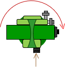
Rotate the instrument 180° and check the ground point through the plummet, Figure G-15(a).
 |
 |
 |
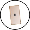
| (a) Rotate 180° | (b) On ground point | (c) Off ground point |
| Figure G-15 Instrument Rotated |
||
If it is still on the ground point, Figure G-15(b), it is correctly adjusted.
If the plummet it is pulled off the ground point, Figure G-15(c), then it is maladjusted.
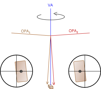
The only part of the OPA which can be adjusted is the crosshair reticule in front of the observer's eye. A maladjusted plummet means the crosshairs are either too high or too low so the horizontal segment of the OPA is not horizontal. Because the OPA is bent 90° thru a prism, the vertical segment of the OPA is not vertical, Figure G-16.
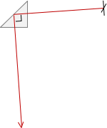 |
| Figure G-16 OPA Maladjustment |
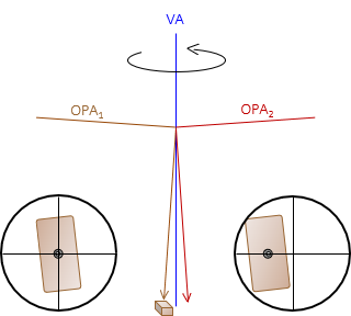
So how much error is there? When the instrument was reversed, the amount the mark moved off the point is twice the error, Figure G-17.
 |
| Figure G-17 Maladjusted Optical Plummet |
The instrument is vertically over a point halfway between the ground point and the current plummet sight location, Figure G-18.
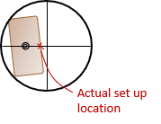 |
| Figure G-18 Instrument Location |
(3) Compensation
(a) Procedural
i. By Setup
Carefully loosen the instrument attaching screw.
While sighting through the plummet, slide the instrument across the tripod head halfway back to the ground point.
Tighten the instrument attaching screw.
Rotating the instrument to various positions and checking the plummet shows it follows a circular path centered on the ground point, Figure G-19.
 |
| (a) Set up |
| (b) Plummet Path |
| Figure G-19 Procedural Compensation |
ii. By Plumb Bob
Use a plumb bob to center the instrument over the ground point. A plumb bob will hang vertically regardless optical plummet condition.
(b) Adjustment
The adjusting screws for the optical plummet crosshairs are located forward of the eyepiece. There may be one to four screws, Figure G-20, and they may be exposed or under a cover.
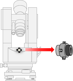 |
| Figure G-20 Adjusting Screws |
To correct the OPA with the adjusting screws:
- If not using a plumb bob, then bring the crosshairs back half the amount of their reversed instrument position. Recenter the instrument and check.
- If using a plumb bob, center the instrument with the plumb bob, then bring the crosshairs to the ground point. Reverse the instrument and check.