3. Personal
a. Centering
(1) Description
The angle desired is the one defined by the ground points. To measure that angle requires an instrument, TSI or sighting mark, be set up at some height above each point. The center of the instrument should be exactly vertically above the ground point.
- The TSI is oriented using either an optical plummet or plumb bob and, while close.
- Sighting marks may consist of freely suspended plumb bobs, reflector poles with built in bubbles, or tripod/tribrach-mounted target each with its own centering challenge.
Figure D-3 shows the relationship of centering errors on an angle measurement.
 |
| Figure D-1 Centering Errors |
(2) Behavior
Centering errors, individually and cumulatively, behave randomly.
(3) Compensation
Although the error is never fully eliminated, TSI centering over a point gets better with practice. The same is true with a tripod mounted target.
Pole mounted targets generally have larger centering errors unless a pole bipod or tripod is used. Keeping a handheld pole as short as possible reduces the error from pole wavering. For stability, a second pole or lath can be used as a support, Figure D-4, on windy days.
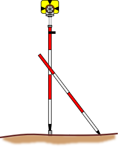 |
| Figure D-4 Stabilizing a Reflector Pole |
b. Pointing
(1) Description and Behaviors
Pointing error depends on how accurately the TSI operator can sight (point) at the BS and FS marks. A number of things affect this, the most significant being:
- Parallax
- Target width
- Target distance
Parallax
The effect and removal of parallax been discussed before. By now the operator should be familiar with its behavior and how to remove it. Even though its affect is random and it's instrument based, failure to remove it is a personal error.
Target width and distance
Although these are separate characteristics they are related because in combination they affect the sight mark's relative size. Figure D-5 shows the same reflector pole sighted at two different distances. The closer the pole is, the more difficult to center the cross hair on it.
|
(a) Distance = x |
(b) Distance = 2x |
| Figure D-5 Pointing Error |
|
At shorter distances, a narrower sight mark, such as a plumb line, should be used for more accurate pointing.
How much pointing error could we expect? As an extreme, consider sighting the edge of a target rather than its center, Figure D-6.
 |
| Figure D-6 Sight Distance and Angular Error |
Table D-1 shows the error for two different target types at varying distances. The targets are a 0.10 ft diameter reflector pole and a 0.03 ft diameter pencil.
| Table D-1 | ||||
| Reflector pole | Pencil | |||
| dia = 0.10 ft | dia = 0.03 ft | |||
| Dist (ft) | Accy: 1 in | Angle, a | Accy: 1 in | Angle, a |
| 100 | 2,000 | 0°01''43" | 6,670 | 0°00'31" |
| 200 | 4,000 | 0°00'52" | 13,300 | 0°00'15" |
| 300 | 6,000 | 0°00'34" | 20,000 | 0°00'10" |
| 500 | 10,000 | 0°00'21" | 33,300 | 0°00'06" |
| 1000 | 20,000 | 0°00'10" | 66,700 | 0°00'03" |
At shorter distances, the error could be quite substantial if the target edge was sighted instead of its center. At those short distances, it wouldn't be very likely that the edge would be sighted but centering the cross hair on a larger target does become less accurate.
The novice surveyor will notice that angle repetition is harder with larger D/R angle spreads in situations when either or both of the sights are short.
(2) Minimizing
Pointing error is a random error so we can't expect to eliminate it entirely, but it can be minimized with careful target selection and use. In addition to parallax removal, to minimize sighting error requires proper target selection, Figure D-7:
- At shorter distances, "finer" targets should be used.
- When using a rigid target that is in contact with the ground mark, such as a reflector or range pole, sight as low on the target as possible.
- A handheld plumb bob should be held as low and as near the point as possible to minimize swing and better center it.
- Sight the line closer to the support of a plumb bob suspended from a tripod where swing is least.
- For a tribrach mounted target, sight directly on the target.
 |
 |
 |
 |
| Figure D-7 Proper Sighting |
|||
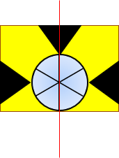
What about using the reflector glass center where the lines of the individual prisms intersect? That's fine when the reflector is perpendicular to the sight line, Figure D-8(a). However, when it's rotated, even slightly, Figure D-8(b), a horizontal offset is introduced because the assembly has depth and prism facets intersect is vertically offset.
 |
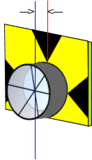 |
| (a) Front | (b) Rotated |
| Figure D-8 Sighting Reflector |
|