I. Error Sources
There are many potential errors in aerial imagery. This chapter identifies the most common when making measurements on individual photographs whether in physical or digital form. Most appreciable errors result from image resolution, reference framework, and image stability.
1. Resolution
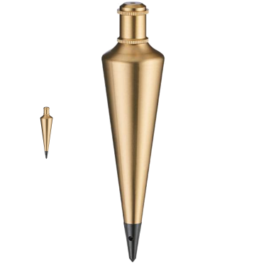
Figure I-1 shows a plumb bob, a distinct object, at 1x and 5x magnifications. When viewed at higher magnification, the bob appears larger and more of its detail is visible.
 |
| Figure I-1 Plumb Bob Magnification |
The plumb bob is a real object with a specific level of detail that becomes more visible under increasing magnification.
An aerial image is a representation of real objects captured at a specific resolution. Object details are limited by image resolution: with film it is the emulsion grain size, with digital it's pixel size.
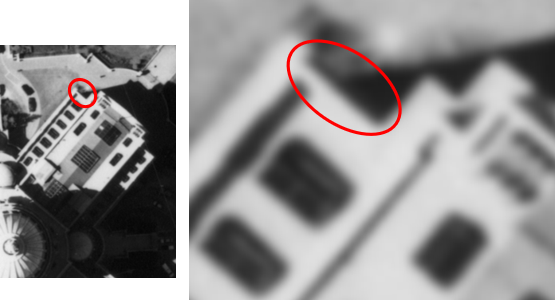
Unlike the plumb bob, magnifying the image does not increase object detail. Figure I-2 is a portion of an 9"x9" aerial photograph at 1x and 6X magnification levels. The same building edge is circled in each.
 |
| Figure I-2 Air Photo Magnification |
At increased magnification the object gets larger, but the detail level does not increase. It looks blurry because we're approaching the film resolution level.
Figure I-3 is a digitally captured aerial image of a building and parking lot at 1x and 20x magnification levels.
|
|
| Figure I-3 Digital Image Magnification |
The larger magnification was used in order to show the image pixels. The right image is the three vehicles circled on the left image. As with the photo, objects size increases but detail level does not.
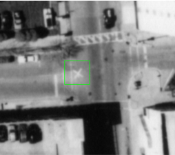
How large are the pixels? The image is part of a countywide aerial digital mapping project. Contract specifications were 1.5 ft rural area image resolution and 0.5 ft urban area resolution. The image is of the University of Wisconsin campus in the city of Platteville so each pixel is 0.5 ft by 0.5 ft. Point objects smaller than the pixel size may have to be identified by other information. For example, utility and light pole positions can be identified by radial displacement and shadows. Others may be harder or impossible. Water valve covers, fire hydrants, survey monuments, and drop inlets are at or below pixel size. If such objects are important to locate on an image (digital or photo), they should be marked with targets before image capture. Figure I-4 shows a targeted horizontal control point (nail in pavement) from an 9 in by 9 in aerial photo flown at approximately 2000 ft above ground level.
 |
| Figure I-4 Aerial Target |
Image resolution limits measurement accuracy. The only ways to increase image resolution is by re-flying the imagery at lower altitude and/or using a scanner with a denser sensor array. Software packages which analyze pixel group characteristics giving sub-pixel level positions generally use sophisticated interpolation algorithms without increasing actual detail.
2. Reference Frame
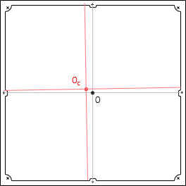
The origin of the photo coordinate system is at the intersection of straight lines connecting opposite side fiducial marks. This intersection should coincide with the principal point, the location where the optical axis intersects the focal plane. However, the actual principal point, OC, might not coincide with fiducial line intersections; it could be offset in the x and y directions and the axes rotated, Figure I-5.
 |
| Figure I-5 Principal Point Error |
Measured photo coordinates should be be adjusted for the offsets and axes skewness.
If calibrated coordinates of the fiducials are available, point coordinates can be determined by measuring from two (or more) fiducials, Figure I-6, then applying trigonometry to determine corrected coordinates.
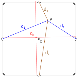 |
| Figure I-6 Coordinates from Fiducials |
The additional measurements and computations may or may not be necessary based on accuracy needs.
3. Photo Coordinates
Rarely is a flightpath perfectly straight, Figure I-7, particularly in a strip of three or more photos.
 |
| Figure I-7 Curved Flight Path |
When a steroplotter is used for map compilation the diapositives are mounted and then subject to Relative and and Absolute orientations. Relative orientation builds the 3D neat model, recreating the geometry at expossure, including the fligh path. Absolute orientation locates the model correctlty in 3D space.
Measuring directly on paper prints generally means using the photo's fiducial coodrinate axes, Figure I-8. This is fine for some lower accuracy appliucations.
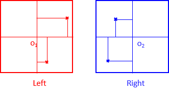 |
| Figure I-8 Fiducal Axes |
Recall that parallx is defined as the image position shift between two photos in the direction of flight. In Figure I-8, the y-coordinate of both points should be the same on both photos (subject to measurement erros, of course). If they're appreciably different, then there is an unaccounted error.
The x-axes on the photos should be in the flight direction, the y-axie perpendicular to it. To define the axes system, each photo's principle point is located on the other photo. Connceting them defines the flight direction on each photo, Figure I-9. This is each photo's x axis.
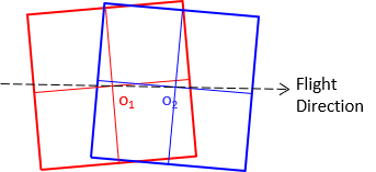 |
| Figure I-9 Transferring Principle Points |
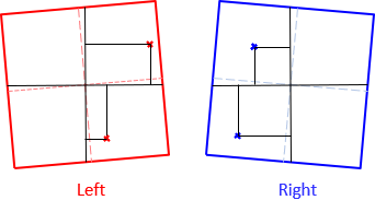
The y axes is perpependicular to the x-axes through the principle point. Coordinate measurements are made with respoect to this new coordinate system, Figure I-10.
 |
|
Figure I-10 |
4. Lens Distortions
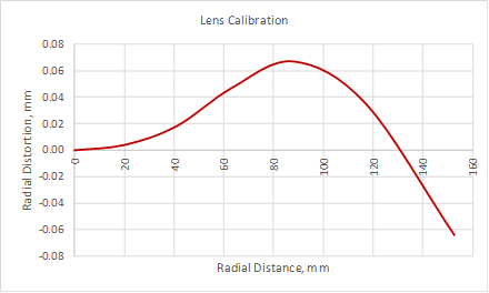
Chapter H. General Optics in I. Basic Principles discusses lens characteristics, basic optical relationships, and distortions. Those relationships and distortions apply to the lens system of an aerial camera. When a camera is calibrated its radial and tangential imgae displacements are determined across the entire focal plane.
Figure I-11 is an example of radial lens distortion calibration data for a camera.
 |
| Figure I-11 Radial Lens Distortion |
5. Media Stability
The fiducial framework is a physical part of the camera. Film does not have the dimensional stability of the camera so the medium can expand or shrink with temperature change. A sensor array, being part of the camera, does not have this problem. Whether film or sensor, creating a physical positive image requires another medium. Depending on the medium composition and method of positive image creation, differential expansion or shrinkage may occur.
The only way to determine the amount of expansion or shrinkage is by comparing measurement distances between fiducial marks to calibrated values. Any change represents systematic behavior so a correction can be applied if it is sufficiently significant.
Image coordinates can be corrected by:
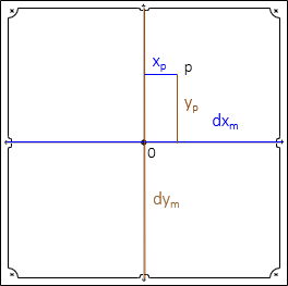
a. Applying shrinkage/expansion to measured coordinates
 |
| Figure I-12 |
Measured coordinates are corrected using Equations I-1 and I-2.
 |
Equation I-1 |
 |
Equation I-2 |
| x'p, y'p : corrected coordinates xp, yp: measured coordinates dxc, dyc: calibrated fiducial distances dxm, dym: measured fiducual distances |
|
b. Measure from fiducial marks
Using the reference frame correction of Figure I-6 will also compensate shrinkage/expansion error.
6. And More....
This Section identifes the most significant aerial imagery errors. There are othes which may affect reults depending application and conditions. For example, high altitude photography may need to account for earth curvature. Altitude and atmospheric conditions may introduce atmospheric refraction. Wind affects not just flight direction but can have effect on altitude and tilt.
As with any measurement system, understanding where errors originate, how they affect measurements, and how to minimze them is critical to ensuring quality results.
