Page 2 of 4
2. Level Circuit LS Adjustment
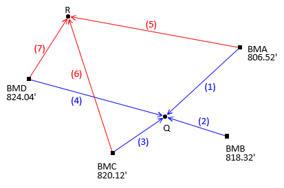
For the leveling circuit in Figure B-1
 |
| Figure B-1 Level Circuit |
and these observed elevation differences
| Obs | Line | dElev | Obs | Line | dElev | |
| 1 | BMA-Q | +8.91 | 5 | BMA-R | -3.56 | |
| 2 | BMB-Q | -2.92 | -- | -- | ||
| 3 | BMC-Q | -4.67 | 6 | BMC-R | -17.12 | |
| 4 | BMD-Q | -8.66 | 7 | BMD-R | -21.10 |
what are the elevations of points Q and R?
A traditional simple adjustment is difficult to apply in this situation. Because point Q is connected to four benchmarks and point R to three, any simple adjustment attempted will result in multiple elevations for each point.
With a small network like this, a Brute Force approach might be feasible. Using the observed elevation differences, compute all possible elevations for points Q and R, then simply average them.
Point Q elevations and their average are:
Similarly, for point R:
Compute So
Compute residuals using the adjusted elevations and the individually computed elevations used for the averages.
| v = MPVQ-ElevQ | v2 | sums |
| -0.015 | 0.000225 | |
| +0.015 | 0.000225 | |
| -0.035 | 0.001225 | |
| +0.035 | 0.001225 | 0.002900 |
| v = MPVR-ElevR | v2 | |
| +0.007 | 0.000049 | |
| -0.033 | 0.001089 | |
| +0.027 | 0.000729 | 0.001867 |
| 0.004767 |
There are seven observations (m) and two unknown elevations (n).


