2. Measuring a Horizontal Angle
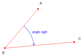 |
| Figure C-2 Example Angle Measurement |
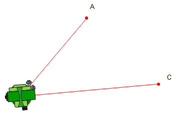
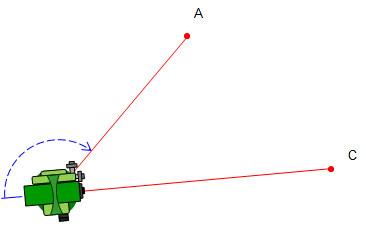
This section will describe an angle measurement procedure and recording the readings. In our example, the TSI will occupy point B and measure the angle right (clockwise) from A to C, Figure C-2.
There are various note formats which can be used depending on the project and other measurements being made. Running a traverse, for example, would use a format which incorporates distances as well as angles.
For this example, we will use a simple angle only format.
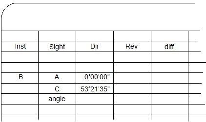
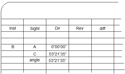
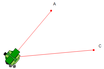
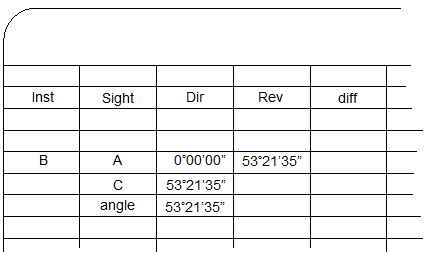
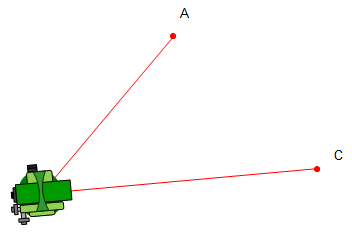
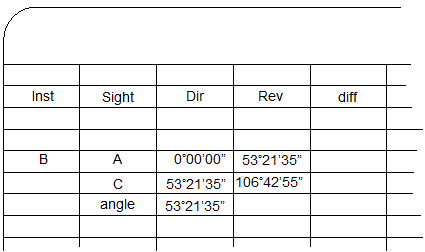
The procedure and notes are shown in Figure C-3.
Click here for a video of this example.
|
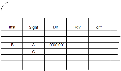
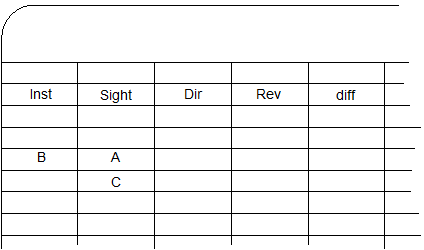
Set up the column headings.
|
 |
|
The TSI is set on point B. |
|
|
|
|
|
The lock is released and TSI rotated in the direction of the angle to point C. In this case, to the right. |
|
 |
 |
|
The value of the angle is the difference between the FS and BS readings. Compute and record it immediately after the FS reading is made. This is the direct angle. |
 |
 |
The telescope is reversed about the HA so it points away from C. Then the horizontal lock is loosened and instrument rotated to the right back to point A. |
|
Using the lock and slo-mo, point A is accurately sighted. |
|
 |
 |
|
The lock is released and TSI rotated right to point C. |
|
 |
 |
|
The value of the reverse angle is the difference between the FS and BS readings. The direct and reverse angle should be close. Their difference should be primarily due to instrumental and pointing errors. The difference is recorded in the diff column. |
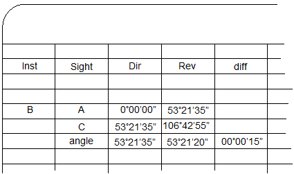 |
|
The process would be repeated for the number of D/R sets required. Successive direct and reverse angle sets should be relatively consistent taking into account random errors. |
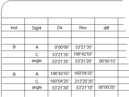 |
| If all the angles are within acceptable limits, the final angle is computed as the average of all the D/R angles. |  |
| Figure C-3 Angle Measurement Process and Notes |
|
