B. Camera
1. General
A photogrammetric camera is considerably larger and more complex than a hand-held or cell phone camera. Film as the image capture medium has been largely replaced by a digital detector array, but the general camera characteristics and terminology are the same.
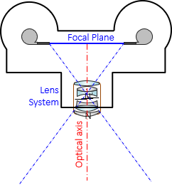
Figure B-1 is stylized version of an airborne mapping camera.
 |
| Figure B-1 Aerial Camera |
The film or sensor array is located on the focal plane, where the image comes to focus. At typical flying heights, the image distance and focal length are the same.
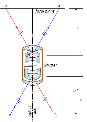
The camera uses a fixed-focus lens system, Figure B-2, due to the flying speed and and height.
 |
| Figure B-2 Lens System |
The lens system's front and read nodal points, N and N', serve as the reference points for measuring object, image, and focal distances. Each light ray enters the front nodal point and emerges from the rear nodal point parallel with its original direction.
Most traditional mapping cameras used a 6.00 inch nominal focal length lens, with some as short as 3.5 inches, others up to 9 inches.
2. Image Coordinate System
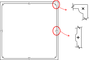
Metric photogrammetric cameras use a 9 inch square film format. The frame surrounding the negative at the focal plane contains fiducial marks located at the middle of each side; some cameras include corner fiducials, Figure B-3.
 |
| Figure B-3 Fiducial Marks |
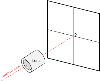
Connecting opposite fiducial marks defines the image's coordinate system. The axes should intersect at the principal point, o. The principal point is at the perpendicular intersection of the optical axis and focal plane, Figure B-4.
 |
| Figure B-4 Principal Point, o |
3. Calibration
As with any measuring instrument, a camera is subject to instrumental errors. Aberrations and distortions are one group of errors. The fiducial marks are another: do the axes intersect at right angles? Does their intersection, Figure B-5, coincide with the principal point? Does the optical axis intersect the focal plane at right angles?
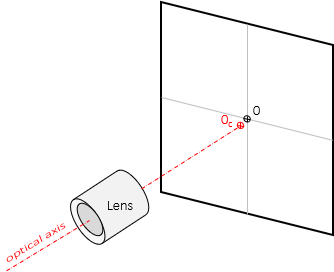 |
| Figure B-5 Principal Point Calibration |
A camera calibration includes information to compensate systematic errors. These include geometric camera attributes (focal length, fiducial coordinates, principal point coordinates, etc) as well as lens distortion behavior. For example, the following is calibration data for a Wis DOT mapping camera.
| Camera Serial No. | 266611B |
| Focal length | 152.2650 mm |
| Principal point x | -0.0020 mm |
| Principal point y | -0.0040 mm |
Fiducial coordinates

| Side | x, mm | y, mm | Corner | x, mm | y, mm | |
| A | -112.0120 | 0.0030 | E | -110.0080 | 110.000 | |
| B | -0.050 | 111.9850 | F | 109.9950 | 109.9920 | |
| C | 111.9940 | -0.0030 | G | 109.9930 | -110.000 | |
| D | -0.0040 | -111.9950 | H | -110.0080 | -110.000 |
Although basic ground information can be determined using an image and general camera data, more accurate results are possible with calibration data.
Performing a camera calibration is beyond the scope of the material presented herein. Any photogrammetry text will have an extensive discussion of calibration processes as well as use of the data.
4. Field of View
A camera's field of view is the angle at the lens's rear nodal point between light rays intersecting the image plane's opposite corners. The corner fiducials are used to determine the angle, Figure B-6.
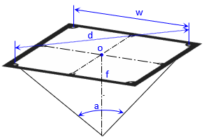 |
| Figure B-6 Field of View |
The field of view, a, is computed using Equation B-1:
 |
Equation B-1 |