5. Tribrach
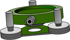
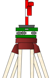
There are two types of tribrachs depending whether an optical plummet is included. One serves as the base of a total station or theodolite and does not have an optical plummet because it is built into the instrument. The second has a fixed, built-in optical plummet allowing it to be independently set up and leveled over a point, Figure B-11. It is generally used for interchangeable equipment such as targets and reflectors.
We'll refer to the first as Type A , the second Type B.
|
|
| Figure B-11 Type B Tribach |
a. Circular Bubble
The circular bubble is used to roughly level the tribrach. Both tribrach types have circular bubbles however there can be slight differences in how they are checked. For both types, the circular bubble is fixed and does not rotate with the instrument so we can't use the reversion principle to check its adjustment.
(1) Type A
Precisely level the attached instrument using its tube bubble. Check the circular bubble, Figure B-12.
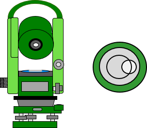 |
| Figure B-12 Circular Bubble Check |
The amount the bubble is not not centered is the error in the bubble. Center it using the adjusting screws. These are located either underneath the bubble housing or around the perimeter of the bubble. If they are capstan-headed screws, Figure B-13, use the correct size adjusting pin from the instrument's toolkit. If the pin is missing, select a thin nail or drill bit shank. Use one as close to the hole size as possible to avoid elongating the holes.
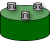 |
| Figure B-13 Capstan Screws |
(2) Type B
Most Type B tribrachs can be attached to a theodolite or total station in place of the instrument's tribrach. The circular bubble can then be checked and adjusted as a Type A tribrach.
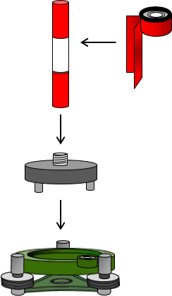
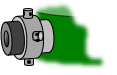
If the tribrach cannot be attached to a compatible instrument, then a calibration set up can be created as shown in Figure B-14(a). This requires a tribrach reflector adapter with a threaded mount stem, a short sight pole ("candy cane") or range pole section, and an adjusted rod bubble. Attach the pole to the adapter and lock the adapter in the tribrach. Attach the tribrach to a stable tripod setup. Holding the rod bubble against the pole, center it using the tribrach leveling screws, Figure B-14(b).
 |
 |
| (a) Parts | (b) Checking |
| Figure B-14 Short Pole |
|
The bubble error is the amount it is out of its circle, if any. Center the bubble using its adjusting screws.
This method can also be used for Type A tribrachs.
b. Optical plummet
(1) Type A
Because the optical plummet is built into the instrument rather than the tribrach, checking and adjusting it is discussed in Chapter D. Total Station Checks.
(2) Type B
Since the line of sight through the plummet includes the plummet mark and ground point, be sure to clear parallax. There are two focusing rings, one for the plummet mark and the second for the ground point. Use the same method to clear parallax as for an instrument's main telescope.
The optical plummet does not rotate so we can't use the reversion principle. However, checking the plummet is easy as long as a tripod with a plumb bob hanger is used. The optical plummet axis should be vertical when the tribrach is level. Because vertical is defined by gravity's direction, the plummet axis should also coincide with a freely suspended plumb bob.
To perform the check:
- Attach the tribrach to a tripod set up over a ground point.
- Suspend a plumb bob from the tripod's instrument attachment screw.
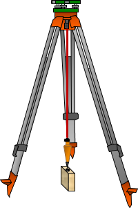
- Using the plumb bob, center the tribrach over the ground point, Figure B-15.
 |
| Figure B-15 Center Over Point |
- Level the tribrach using its circular bubble and leveling screws (do not extend/shorten tripod legs).
- Check to make sure the plumb bob is still over the point; shift the tribrach if not.
- Remove the plumb bob and sight through the optical plummet.
- If the plummet mark is on the ground point, no adjustment is needed.
- If the plummet mark is not on the mark, Figure B-16, it is maladjusted.
- The error is the distance between the marks.
- Use the optical plummet adjusting screws, Figure B-17, to move the plummet mark to the ground mark.
- There can be 1, 2, or 4 adjusting screws and they may be exposed or under a cover depending on the instrument.
 |
 |
|
| Figure B-16 Maladjusted |
Figure B-17 Adjusting Screws |
Because this check is dependent on the plumb bob, it is important that the correct hanger is used with the tripod. The hanger may be an insert or clip-in. Do not use a home-made hanger because the plumb bob might hang offset from the correct vertical line.