E. Electronic Distance: Combined Constant
1. Combined Constant
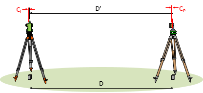
An EDM distance is the sum of the measured distance and the instrument and reflector constants, Figure E-1.
 |
| Figure E-1 Instrument and Reflector Constants |
| D = D'+(CI+CP) | Equation E-1 | |
|
D: corrected distance |
||
k is the Combined Constant. Because it is internal, most instruments compensate for CI. The surveyor needs only to input the reflector constant; typical values are 0 mm and 30 mm. Over time the TSI may lose calibration and rough reflector handling require determination of a new constant to use.
2. Calibration
a. National Geodetic Survey (NGS) Baseline
The most rigorous way to determine the combined constant is to use an NGS calibration baseline following its calibration procedure. Baseline data and procedures are available at https://www.ngs.noaa.gov/CBLINES/calibration.shtml on the NGS web site.
b. Local baseline
Calibration using an NGS baseline is a very time- and computation-intensive process. A quick, simple, and accurate calibration can be performed by setting up a temporary local three point baseline.
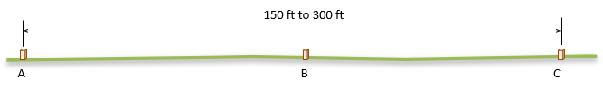
(1) Baseline
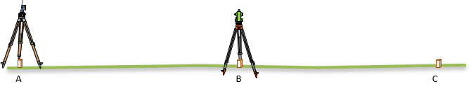
On open relatively flat terrain set three points (A, B, & C) on a straight line. The outer two points (A & C) should be 150 to 300 feet apart; the inner point (B) should be near the midpoint of the line. Point B does not have to be at the exact midpoint but all three points must be on a straight line, Figure E-2.
 |
| Figure E-2 Calibration Baseline |
It is very important that the three points be in a straight line. If they aren't, a very flat triangle is created which will cause an error in the constant determination.
A good way to ensure all three are on line:
- Set point A
- Set point C
- Set up the instrument over point A.
- Sight point C
- Lower the telescope to set point B
(2) Pre-calibration preparation
The reflector must be mounted on a tribrach and tripod or pole with pole bipod. Manually holding a reflector pole will introduce too much random error.
When set up, the reflector should be at approximately the same elevation as the instrument for a near horizontal measurement. A few degrees off horizontal in either direction will not affect the calibration over such short distances.
Set the reflector constant to 0 on the instrument and apply appropriate atmospheric settings before making any measurements.
If calibrating a total station instrument (TSI), measure distances in the direct and reverse positions for best accuracy.
(3) Procedure
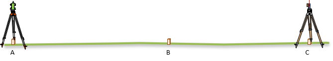
(a) Set up the instrument at point A and reflector at point C, Figure E-3.
 |
| Figure E-3 Distance AC |
Measure the distance to point C multiple times.
Compute the average distance AC.
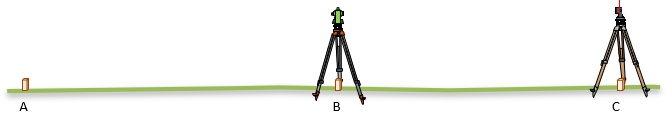
(b) Move the instrument to point B, Figure E-4.
 |
| Figure E-4 Distance BC |
Re-setup (ie, re-center and re-level) the reflector at point C to ensure an independent measurement.
Measure the distance to point C multiple times.
(c) Move the reflector to point A, Figure E-5.
 |
| Figure E-5 Distance BA |
Re-setup the instrument at point B.
Measure the distance to point A multiple times.
Compute and record the average distances BA and BC.
(4) Compute k
The combined constant, k, affects all three measurements. Since the instrument reflector constant was set to a 0, we expect a disparity between the total distance AC and the sum of its parts BA+BC, Equation E-2.
|
AC+k = (BA+k) + (BC+k) |
|
| k = AC - (BA + BC) | Equation E-2 |
(5) Repeat
Re-run the calibration and computation - be sure to re-set the instruments so not to repeat the same errors. k should be consistent within reasonable instrument and reflector centering errors.
If the second constant differs significantly from the first, either a mistake has been made or the instrument may require repair. Run the calibration a third time to determine the case.
What is a "significant" difference? k is the result of six instrument setups. If each setup has the same centering error, the expected error in k can be computed from an Error of a Series, Equation E-3.
 |
Equation E-3 |
For example: if the centering errors for the instrument and reflector are ±0.005 ft, the expected error in k would be:
| Equation E43 |
When comparing two k's, the expected error in their difference should be within:
| Equation E-3 |
A difference outside ±0.017 could be considered significant.
If the difference is acceptable, use the average k.
(6) Apply
Make note of k and use in place of the reflector constant for that particular instrument and reflector combination.
If different reflectors are used with a single instrument, each combination should have its own combined constant determined, recorded, and applied.