4. Meridian Convergence
a. Meridian Orientation
Non-magnetic meridians are either parallel or convergent. For Plane Surveying applications over smaller areas and in assumed systems, parallel meridians are used, Figures C-24.
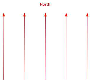 |
| Figure C-24 Parallel Meridians |
In a parallel meridian system, there is no singular unique north point.
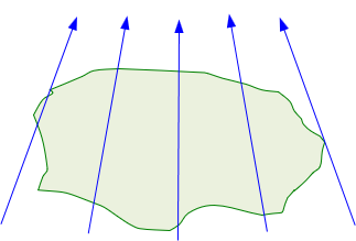
For Geodetic Surveying applications, where the earth's shape is taken into account, Figure C-25, meridians converge to a particular north point, Figure C-26.
 |
| Figure C-25 Earth Shape |
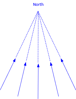 |
| Figure C-26 Convergent Meridians |
Depending on the geodetic reference system, the north point may be
- True (aka Geographic) - based on the earth's average rotational axis (the earth wobbles as it rotates).
- Astronomic - based on gravity and celestial observations (using either Polaris or the Sun).
- Geodetic - based on a particular mathematical earth model.
For purposes of this Chapter, we'll limit discussion to the northern hemisphere. In the southern hemisphere, meridians converge to a south point, reversing things by 180°.
b. Forward and Back Directions
In Chapter A. Definitions, it was stated that
- A forward and back bearing had the same angle from the meridian but opposite quadrants
- A forward and back azimuth differed by 180°
These are true only for parallel meridians. When meridians converge, the forward and back direction angles must account the convergence.
Bearings
Figure C-27 shows the geometry for the bearing and back bearing of line AB.
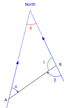 |
| Figure C-27 Forward-Back Bearing |
The forward bearing is N α E, the back bearing is S β W. The angular convergence between meridians is θ.
From the geometry in Figure C-27:
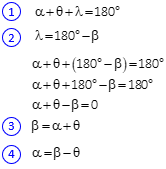
The last two equations show that the forward and back bearing angles differ by the convergence.
Azimuths
The geometry for the azimuth and back azimuth line EF is shown in Figure C-28.
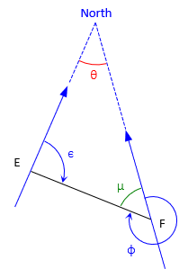 |
| Figure C-28 Forward-Back Azimuth |
The forward azimuth of line EF is ε, the back azimuth is φ. θ is the angular convergence between the meridians.
From the geometry in Figure C-19:
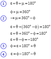
The last two equations show that the 180° difference between the forward and back azimuths must be adjusted by the convergence.
c. Grid Systems
A formal grid coordinate system covers an area large enough that convergence of true meridians, Figure C-29, must be taken into account.
 |
| Figure C-29 Converging True Meridians |
The coordinate system uses a Grid North axis and a perpendicular Grid East axis. Grid north meridians, Figure C-21, are parallel with the Grid North axis.
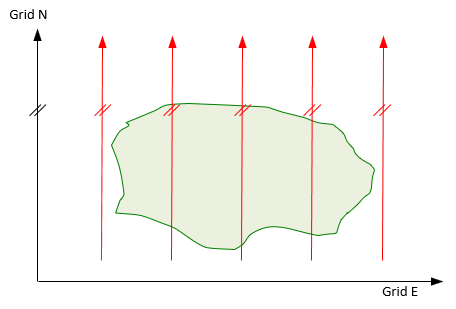 |
| Figure C-30 Parallel Grid Meridians |
Figure C-31 shows the grid meridians overlaid on the true meridians.
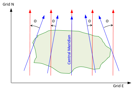 |
| Figure C-31 Varying Convergence |
The grid system is centered on the area so grid north and true north coincide along the central meridian. Moving east or west of the Central Meridian, grid meridians remain parallel while true meridians do not. The further from the Central Meridian, the greater the convergence angle.
In a grid system, convergence is from the true meridian to the grid meridian. East of the Central Meridian convergence is positve, west it is negative.
Example
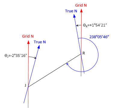
The true azimuth for line RJ is 238°05'46". The convergence at point R is +1°54'21", at J it is -2°35'16".
Compute: (a) Grid azimuth from R to J, and (b) True azimuth from J to R
Sketch of provided information
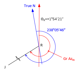
(a) Grid azimuth from R to J
Sketch
![]()
(b) True azimuth from J to R
Sketch
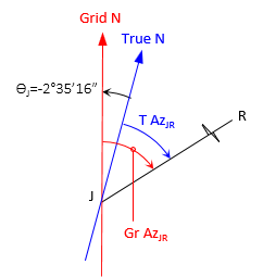
Because grid north meridians are parallel, the grid azimuths of RJ and JR differ by exactly 180°.
![]()
![]()
The difference between the true azimuths of RJ and JR is:
![]()
This is 4°29'37" greater than 180°00'00" and is the sum of the absolute values of the convergences. The effect of convergences on forward and back true directions are:
- If convergences are in opposite directions, the forward and back true azimuths differ from 180° by the sum of the convergence absolute values.
- If the convergences are in the same direction, the forward and back true azimuths differ from 180° by the difference of the convergences.