E. Bubbles, Axes, and Optics, Oh My!
1. Bubbles
Most surveying equipment has a bubble to facilitate being correctly oriented to gravity. Two kinds of bubbles are used: bubble tube and circular bubble. Figure E-1 shows top and side view of both.
|
Top View |
|
|
|
|
|
Side View |
|
|
|
|
|
a. Tube |
b. Circular |
|
Figure E-1 |
|

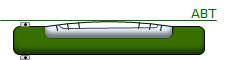
The axis of the bubble tube (ABT) is a line tangent to the center of the upper curved surface of the bubble, Figure E-2.
|
|
|
|
a. Tube |
b. Circular |
|
Figure E-2 |
|

Technically, since a circular bubble is spherical, the ABT is actually a plane, Figure E-3, but we can refer to its edge view as the ABT.
|
|
|
Figure E-3 |

Bubble sensitivity is an expression of surface flatness. It is the angle at the curvature center for a specific surface distance, usually 2 mm, Figure E-4.
|
Figure E-4 |
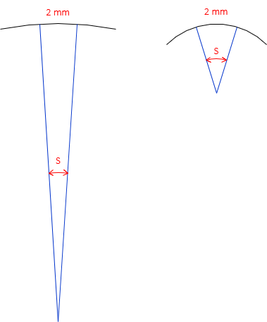
A less curved (flatter) surface has a larger radius and smaller angle than a more curved surface. A flat surface means the bubble responds more quickly (is more sensitive) to vertical movement. Most contemporary tube bubbles have a sensitivity in the range of 20" to 30 ", a circular bubble is typically 10'.
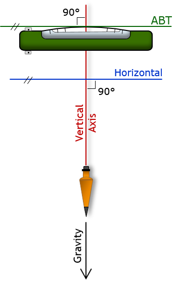
2. Vertical Axis
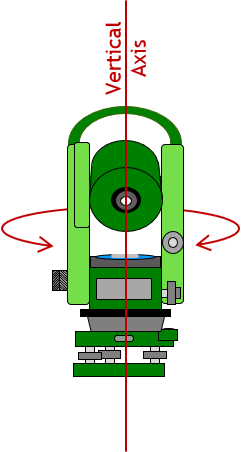
The vertical axis, VA, of an instrument is the line about which the instrument is rotated horizontally. Figure E-5 shows a total station instrument and automatic level with their respective Vertical Axes.
|
|
|
|
a. Total Station |
b. Automatic Level |
|
Figure E-5 |
|
On a correctly adjusted bubble-based instrument the ABT is perpendicular to the VA. The instrument is oriented to gravity by centering the bubble which makes the ABT horizontal and the VA vertical, Figure E-6.
|
|
|
Figure E-6 |
If the ABT is not perpendicular to the VA then set up error is introduced. In later topics on specific instruments, we will see how to check and compensate for this maladjustment. For now, we will assume the respective instrument is in adjustment.
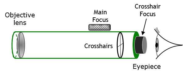
3. Line of Sight
Many, but not all, instruments have a telescope for sighting on a target. The telescope, Figure E-7, is a tube with an objective lens at one end and operator’s eyepiece at the other. Just forward of the eyepiece are the crosshairs (aka, crosswires) which are mounted to the reticle ring. The telescope has a main focusing knob for the objective lens and a focusing ring for the crosshairs.
|
|
|
Figure E-7 |
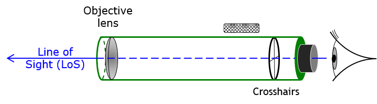
The Line of Sight (LoS) is defined by the optical center of the objective lens and the crosshairs intersection, Figure E-8.
|
|
|
Figure E-8 |
Depending on the instrument, the telescope may rotate in only a horizontal plane or in both horizontal and vertical planes. This will be discussed in the appropriate instrument topics later.
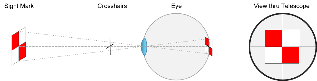
4. Parallax
Looking through the eyepiece, a surveyor sees two images simultaneously: the sighted target and the crosshairs. The target may be hundreds of feet away while the crosshairs are a few inches in front of the surveyor. However, both images must come to focus on the back of the observer’s eye or a condition called parallax will exist.
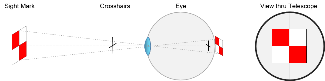
If the image and crosshairs were in perfect focus, we would have the situation shown in Figure E-9.
|
|
|
Figure E-9 |
However, our eyes have a depth of field, like a camera lens, which together with our mind, compensates for varying focal distances of multiple objects. As long as the focal differences fall within the depth of field, the images will appear clear and in focus, Figure E-10.
|
|
|
Figure E-10 |
Look out the window: objects at similar distances will appear in focus. That’s the combination of your eye optics and mind compensating for multiple objects at varying distances. Concentrating on closer objects causes farther ones go out of focus; concentrating on farther objects causes closer ones to get blurry. That occurs because not all object distances can be accommodated by the eyes’ depth of field.
If we take the situation in Figure E-9 and move the eye slightly, there will be an apparent movement of the crosshairs on the object, Figure E-11. That’s because the two images do not come to focus on the back of the eye so do not move together. This shift is called parallax.
|
|
|
Figure E-11 |
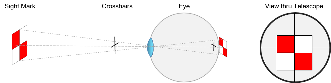
If there is no apparent movement of crosshairs on the target, then there is no parallax - both images are perfectly focused. That's how we test for parallax: focus on the object, then shift your eye. No movement, no parallax.
When using instruments, we don’t want parallax present because it can introduce errors in our sightings or readings. How do we eliminate parallax? The simplest way is:
(1) Adjust the main focusing knob until all images are out of focus.
(2) Using the crosshairs focusing ring, bring the crosshairs into a sharp clear image.
(3) Focus on an object on using the main focusing knob and check for parallax - it should be gone.
By the way: if when you first look through the telescope and can focus on an object but cannot see the crosshairs, use the crosshair focus ring to bring them into view. Then proceed with the paralax clearing method.
Parallax is affected by the geometry of the observer's eye. If a glasses-wearing surveyor clears parallax with glasses on, she may experience parallax with her glasses off and vice versa. Different people will have different parallax conditions: one surveying student checking another's reading may get a different value due to parallax difference. Before taking the first reading of the day, the instrument operator should check for and remove parallax. Every time the instrument operator changes, parallax should be cleared.