{KomentoDisable}
C. Line Directions
1. Traverse Direction Computations
After angles are balanced by whatever method selected, the direction of each traverse line must be determined.
The direction of one line must be known or assumed and by using horizontal angles other successive line directions are computed. The computations were discussed in the Directions topic. Ususally, the same type of angle (interior, deflection, etc) is measured on an entire traverse which can simplify computations somewhat.
a. Computation Method
There are two approaches to compute directions around a traverse: tabular and sketching.
While the tabular method is an efficient systematic approach, for the surveying neophyte it can be confusing and all too easy to flip quadrants. It's not easy to determine if computed directions make sense since there is no visual indication.
Drawing sketches, which was covered in the Directions topic, is slower but allows the surveyor to see line relationships and provides a graphic computations check.
Which to use is largely a matter of preference, but for the beginner sketching is generally a better way to start. All the traverse direction examples and comps in the Surveing Library use the sketching approach.
b. Math Check
Whenever possible, we want to include a math check to catch computation errors.
A loop traverse provides a math check because it closes back on itself. Starting with the first line, we sequentially compute directions around the traverse and then close back on the first line. Its computed direction should match its starting direction. If not, there is a math error (or unadjusted angles were used by mistake).
A link traverse doesn't have a math check unless the directions of its first and last lines are known. This generally insn't the case for most link traverses even if they begin and end on known points. Link traverse computations are covered in Chapter H. Closed Link Traverse.
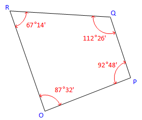
2. Bearings From Interior Angles
Given the following traverse and horizontal angles:
|
|
|
Figure C-23 |
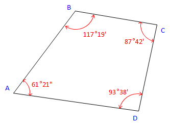
Using a bearing of N 36°55' E for line AB, determine the bearings of the remaining lines clockwise around the traverse.
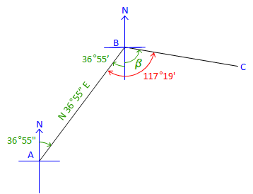
| At point B: | |
|
Figure C-24 |
Label the bearing angle, 36°55', from B to A. Subtract it from 117°19'. β = 117°19' - 36°55' = 80°24'Brg BC = S 80°24' E |
|
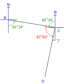
At point C: |
|
|
Figure C-25 |
Label the bearing angle, 80°24', from C to B. Subtract it along with 87°42' from 180°00' to get bearing angle CD. γ = 180°00' - (80°24' + 87°42') = 11°54' Brg CD = S 11°54' W |
|
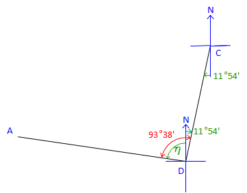
At point D: |
|
|
Figure C-26 |
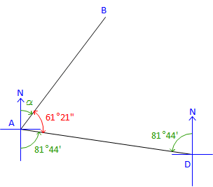
Label the bearing angle, 11°54', from D to C. Subtract it from 93°38' to obtain next bearing angle. &eta= 93°38' - 11°54' = 81°44'Brg DA = N 81°44' W |
|
The directions for all four traverse lines have been computed. Angles at B, C, and D have been used, but that at A has not. For a math check, use the Bearing of DA and the angle at A to compute the bearing we started with. |
|
|
Figure C-27 |
Label the bearing angle, 81°44', from A to D. Subtract it along with 61°21' from 180°00' to get next bearing angle. α = 180°00' - (61°21' + 81°44') = 36°55 Brg AB = N 36°55' E check |
If our computed and initial bearings for AB don’t match it means one of two things:
- there is a math error in our computations, or,
- the interior angles weren’t balanced.
On this traverse the angles sum to 360°00' so there is no angular misclosure. If our math check had failed it would have been due to a math error in our computations.
Had the angles not been balanced and if there were no math errors, the math check would be off by the angular misclosure.
Summary:
| Line | Bearing |
| AB | N 36°55' E |
| BC | S 80°24' E |
| CD | S 11°54' W |
| DA | N 81°44' W |
3. Azimuth from Interior Angles
Given the following traverse and horizontal angles:
|
|
|
Figure C-28 |
Using a azimuth of 68°00' for line OP, determine the azimuths of the remaining lines counter-clockwise around the traverse.
|
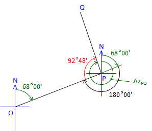
At point P: |
|
|
Figure C-29 |
Line PQ is 92°48' right of Azimuth PO Az PO is the back azimuth of Az OP Az PQ = (Az OP + 180°00') + Angle PAz PQ = (68°00' + 180°00') + 92°48' = 340°48' |
|
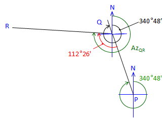
At point Q: |
|
|
Figure C-30 |
Line QR is 112°26' to the right from Az QP Az QP is the back azimuth of Az PQ Az QR = (Az PQ + 180°00') + Angle QAz QR = (340°48'+180°00') + 112°26' = 633°14' Normalize: Az QR = 633°14' - 360°00' = 273°14' |
|
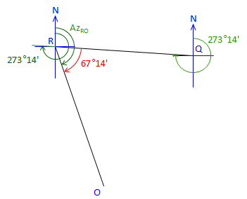
At point R: |
|
|
Figure C-31 |
Line RO is 67°14' right from Az RQ Az RQ is the back azimuth of Az QR Az RO = (Az QR + 180°00') + Angle RAz RO = (273°14' + 180°00') + 67°14' = 520°28' Normalize: Az RO = 520°28' - 360°00' = 160°28' |
|
The directions for all four traverse lines have been computed. Angles at P, R, and R have been used, but not the angle at O. For a math check, use Azimuth RO and the angle at O to compute the original Az OP. |
|
|
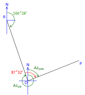
At point O: |
|
|
Figure C-32 |
Line OP is 87°32' right of Az OR Az OR is the back azimuth of Az RO Az OP = (Az RO + 180°00') + Angle O Az OP = (160°28' + 180°00') + 87°32' = 428°00' Normalize: Az OP = 428°00' - 360°00' = 68°00' check! |
Summary:
| Line | Bearing |
| OP | 68°00' |
| PQ | 340°48' |
| QR | 273°14' |
| RO | 160°28' |
There's a distinct pattern computing these azimuths:
New Az = (Previous Az + 180°00') + Angle.
This is true for a loop traverse meeting these conditions:
- Directions are counter-clockwise around the traverse, and,
- Angles are interior to the right.
What if the directions are clockwise around the traverse and interior angles counter-clockwise?
New Az = (Previous Az - 180°00') - Angle
Other patterns exist for clockwise travel with clockwise interior angles, clockwise exterior angles, counterclockwise exterior angles, etc. Rather than memorize the possible patterns, draw a sketch, and begin computing; the pattern will present itself after a few lines.
4. Bearings from Deflection Angles
Deflection angles are measured traveling counter-clockwise around a loop traverse. Starting with an bearing of S 18°45'30" W for line JK, determine bearings of the remaining lines.

(a) Check angular misclosure.
Since this is a non-crossing loop traverse, the deflection angle sum should be ±360°00'00". Right deflection angles are positive, left are negative.

(b) Compute bearings
Depending on bearing quadrants and deflection angle direction, the deflection angle might be added to or subtracted from the previous bearing angle or vice versa to compute the next bearing. While it's possible to set up some rules, it's simpler to draw a sketch to visualize the relationships and computation.
At point K

Line JK's extension through K has the same bearing as line JK.
In this case, the bearing angle is computed by subtracting line JK's bearing from the deflection angle:

Which puts line KL in the SE quadrant:
![]()
At point L

From the sketch, it can be seen that the sum of the previous bearing and deflection angles exceed 180° putting line LM in the NW quadrant:

At point M

In this case, the previous bearing angle is subtracted from the deflection angle:

At point N

This one is a little more convoluted because of the lines and angles geometry.
From the sketch:

At point J
Finally, always compute back into the beginning direction as a math check.


5. Azimuths from Deflection Angles
Deflection angles are measured traveling clockwise around a loop traverse. Starting with an azimuth of 328°58'15" for line AB, determine azimuths of the remaining lines.

(a) Check angular misclosure.
Since this is a non-crossing loop traverse, the deflection angle sum should be ±360°00'00". Right deflection angles are positive, left are negative.

There is no misclosure to distribute.
(b) Compute azimuths
Starting with the azimuth of line AB

Line AB's extension through B has the same azimuth as line AB.
Because the deflection angle to line BC is measured from the extension of line AB, the azimuth of line BC is the azimuth of line AB plus the deflection angle:
 Since the azimuth exceeded 360°, it is normalized by subtracting 360° from it.
Continuing to line CD, we use the same logic: New azimuth = previous azimuth + deflection angle


And so on...
At point D


Finally, at point A compute back into the first azimuth to make sure there are no math errors:


6. Angles from Directions
Examples of computing angles from directions were covered in the VI. Directions topic. When a loop traverse is involved and all its angles are computed, the angle condition should be verified as a math check (always include a math check were possible).
Recall that the angle conditions for loop traverses are:
| Angle type | Condition |
| Interior |  |
| Deflection - Even crossings | |
| Deflection - Odd crossings | |
If the condition is not met, then a math error exists. Go back over your comps.