B. Set Up; Take Down
1. General
Setting up a TSI so that it is level and vertically over the ground point at the same time is one of the most frustrating exercises for the beginning surveyor. Initial patience and continued practice makes the process easier.
Every surveyor has his or her own "right" method to set up a TSI. Some methods are more efficient than others. Any method with which the surveyor is comfortable and accomplishes an accurate set up is a "right" one. The method described here assures a good setup through procedure rather than by depending on luck. It is a two stage process:
- Centering and rough leveling, and,
- Final leveling.
Each process uses a logical progression through discrete steps. At a few places, the surveyor is instructed to
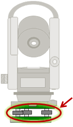 |
| Figure B-1 Leveling Screws |
perform a particular action when an error is encountered (such as a bubble run). These help compensate instrumental errors discussed in Topic XV Chapter G. Theodolite and Total Station.
Before starting, the tribrach leveling screws should be set to mid-run, Figure B-1. This should allow sufficient screw in either direction when leveling.
In most cases, more than one leveling screw must be turned or leg length changed. The novice surveyor should concentrate on a single action at a time otherwise he/she may wind up "chasing the bubble." As experience is gained, the surveyor will be able to perform multiple actions simultaneously to achieve the desired condition.
The tripod must provide a stable platform for the instrument. Hardware should be snug allowing for smooth leg movement and adjustment. Legs must be firmly pushed into the ground - extreme care must be taken if one or more legs has to be placed on concrete. Setting up on asphalt should be avoided. Not only does it create serious heat waves on a sunny day, it is also soft enough that over time a tripod will sink into it disturbing the instrument set up.
Temperature can be an important consideration.
If there is a substantial temperature difference between equipment storage and use, the equipment should be allowed time to acclimate. If not then set up and use errors might occur. For example if a metal tripod, which was in 70° storage, is immediately used in 40° conditions its metal will begin to shrink. The leg locks may initially hold, but over time slip as the metal cools causing the TSI to shift.
TSI cases are often lined with expanded foam. While excellent shock protection, foam can also act as an insulator. The case should at least be opened, even better the TSI removed, in order to allow quicker instrument temperature stabilization. A common temperature change problem occurs if slow motions were locked when the TSI was last put away. The locks should always be released when packing away the TSI.
Take into account temperature differences and allow for equipment acclimation to prevent errors later on.
2. Centering and rough leveling
A good initial tripod location will make the set up process easier. The new surveyor should avoid trying to "carry" a TSI and tripod over a point while looking through the optical plummet and keeping the legs spread. It is not only comical to watch but ultimately a cumbersome way to learn setting up.
The following is a systematic process to center the TSI over the ground point and make it approximately level.
Step (1)
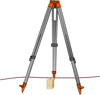 |
| Figure B-2 Setting Up Tripod |
The tripod top should be relatively flat, with the legs spread to provide a stable platform, Figure B-2. First-timers may find it handy to suspend a plumb bob or drop something, like a set of keys, from directly below the tripod head to see where it is with respect to the ground point.
A common beginner's error is setting the tripod too high. While the height makes it convenient for sighting through the optical plummet, the TSI is too high for comfortably sighting through the main telescope.
With the tripod approximately over the point, the legs should be firmly pressed into the ground...
Step (2)
...attach the TSI to the tripod using the mount screw.
The tribrach should be oriented parallel with and centered on the tripod head, Figure B-3.
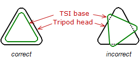 |
| Figure B-3 Aligning TSI on Tripod |
Do not over-tighten the mount screw as it may need to be loosened later to shift the TSI on the tripod head.
The TSI will be neither level nor centered at this point, Figure B-4, but we'll start addressing that in the next step.
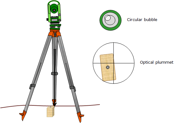 |
| Figure B-4 Attach TSI to Tripod |
Step (3)
Adjust the optical plummet to remove parallax and focus clearly on the ground point.
(See Topic I Chapter E for a discussion of parallax and how to remove it,)
While sighting through the plummet, center it on the ground mark using the TSI's leveling screws, Figure B-5.
When done, the optical plummet will be on the point but the TSI will not be level.
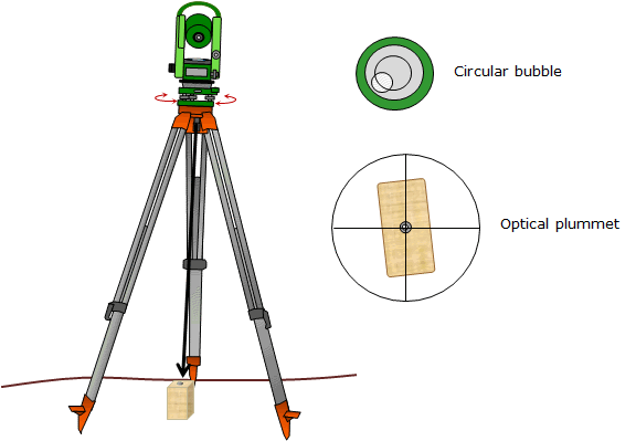 |
| Figure B-5 Center Plummet on Ground Mark Using Leveling Screws |
Step (4)
Center the circular bubble by extending or shortening one or more tripod legs.
It doesn't have to be perfectly centered but the bubble should be entirely within its scribed mark
Adjusting leg lengths moves the TSI in an arc roughly centered on the ground mark. As a result, the optical plummet mark shouldn't move much, if at all, off the ground mark.
Be careful when unlocking a leg - the TSI weight may cause the leg to collapse.
Be sure to fully lock the leg.
Now the circular bubble should be centered and the optical plummet on the ground mark, Figure B-6.
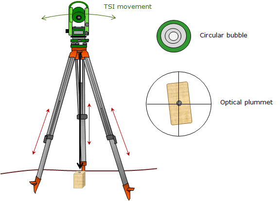 |
|
Figure B-6 |
Step (5)
If the plummet does move off the mark, loosen the instrument mount screw, and, while sighting through the optical plummet, slide the TSI on the tripod top until the marks line up.
Slide to-from and left-right to align the marks, Figure B-7.
Do not rotate the TSI as it is moved - the TSI is leveled with respect to the tripod top and rotating it may cause it to go out of level.
Re-tighten the mount screw.
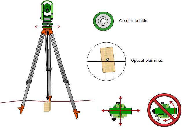 |
| Figure B-7 Slide TSI Left-Right, Back-Forth to Re-center if Necessary |
3. Final Leveling
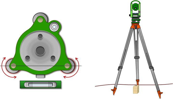
If the circular bubble is in adjustment the TSI will be nearly level. To get it accurately level requires using the tube bubble. Not only is tube bubble more sensitive than the circular one, it also rotates with the instrument so the level can be accurately checked in various directions.
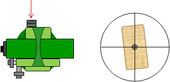
The process of accurately leveling the TSI is based on the principle of reversion and ABT/VA relationship described in Topic XV Chapter G. Theodolite and Total Station. Each step is accompanied with an illustration of a top view of the tube bubble and tribrach showing bubble orientation and leveling screws used.
Step (1)
Rotate the TSI so the ABT is parallel with the line through two leveling screws (it doesn't matter which two).
Using just those two screws, center the tube bubble, Figure B-8
 |
| Figure B-8 Center Tube Bubble Using Two Leveling Screws |
Step (2)
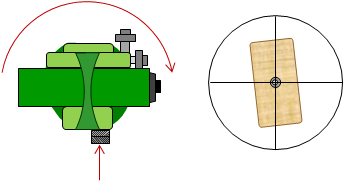
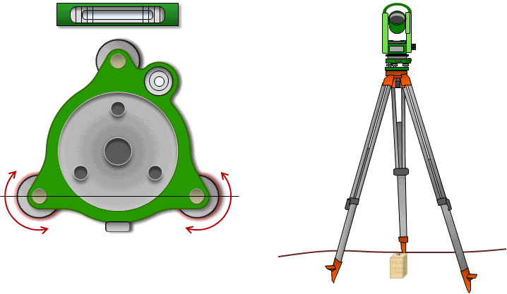
Rotate the instrument 180° so the TSI's position is reversed.
If the bubble runs off center, use the same two leveling screws to bring it halfway back, Figure B-9.
For example, if it runs two divisions, bring it back one division.
 |
| Figure B-9 Rotate TSI 180° and Check Bubble Run |
Step (3)
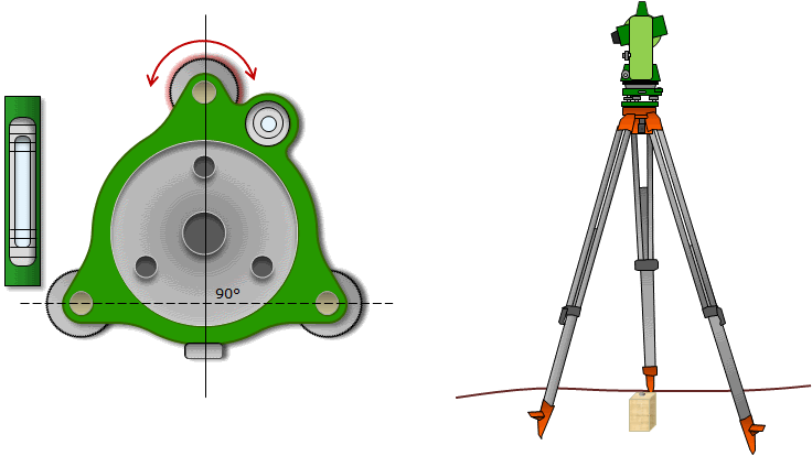
Rotate the TSI 90° so the ABT is at a right angle to the first two screws.
Using only the third leveling screw, center the bubble, Figure B-10.
 |
|
Figure B-10 |
Step (4)
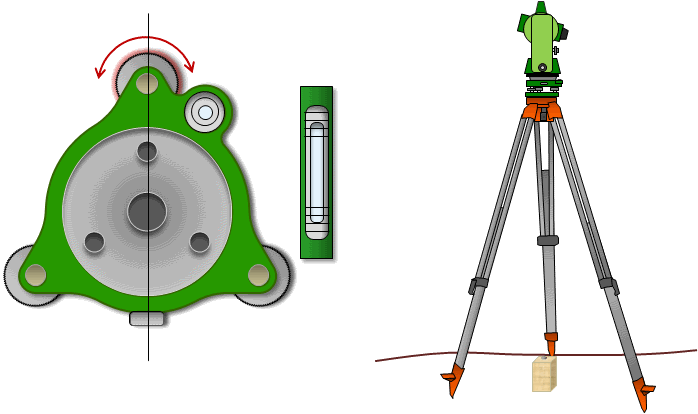
Rotate the TSI 180° so the TSI's position is reversed.
If the bubble runs, bring it back halfway using the third leveling screw only, Figure B-11.
If the bubble ran in Step (2), it should run the same amount in this step. This indicates a systematic error.
 |
| Figure B-11 Rotate TSI 180° and Check Bubble Run |
Step (5)
Check the level in all directions by rotating the TSI.
If the bubble stayed centered throughout the leveling process, then it should stay centered regardless where the TSI is rotated.
If the bubble ran in Step (2) [and (4)] and was corrected back half the run, it should be off that same amount wherever the TSI is rotated.
If it doesn't meet either of these conditions, then there was either a leveling process error or the instrument set up isn't stable.
Step (6)
Check the optical plummet to see if it is centered on the ground mark.
If it isn't, loosen the instrument mount screw and slide the TSI to align the marks.
The TSI should now be accurately leveled and centered over the ground mark. If it is off the mark, loosen the instrument screw and slide the TSI (to-from, left-right) until it is over the point. Re-tighten the screw.
But wait ... the optical plummet could also be out of adjustment so it should be checked.
4. Optical plummet check
Because of the short sight involved, an optical plummet generally doesn't need an adjustment. However the surveyor can't be sure of that without periodically checking it. Fortunately, the check is quick and easy so it should be done as part of the TSI set up. More detail is included in Topic XV. Chapter G. Theodolite and Total Station.
The optical plummet can be checked by TSI rotation or using a plumb bob.
a. TSI Rotation
This method, described in Figure B-12, only works with TSIs whose optical plummets rotate with the instrument.
|
After the TSI is precisely leveled, sight through the optical plummet and mark sure its mark is aligned with the ground mark. |
|
||
|
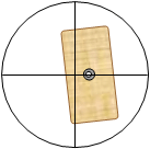
Rotate the TSI 180° to reverse the plummet's position. Check to see if the marks are aligned. If they are, the plummet is in adjustment and the next step can be skipped. |
|
||
|
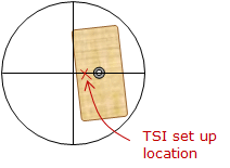
If the marks do not align, the plummet is out of adjustment. The TSI is not set up directly over the ground mark. It is vertically above a point halfway between the ground mark and the current plummet mark position.
|
|
||
| Loosen the instrument mount screw and slide the TSI halfway back to the ground mark. Tighten the mount screw. |
|
||
| Rotate the TSI 180° reversing the optical plummet and sight through it. The plummet mark should still be off the ground mark but on the opposite side. |
|
||
| Figure B-12 Optical Plummet Check |
|||
b. Pumb bob
This method can be used with a fixed or rotating optical plummet and requires a tripod with a plumb bob hanger.
With the TSI attached to the tripod, use the plumb bob to center the instrument. After accurately leveling the TSI make sure the plumb bob is still centered over the ground mark. Remove the plumb bob and sight through the optical plummet. If the plummet is in adjustment it will be centered on the mark. If not centered it shows how much the plummet is out of adjustment.
Because a plumb bob was used for set up the TSI is correctly centered over the ground point so it does not have to be moved.
5. Take down
Before removing the TSI from the tripod the operator should set:
- Vertical and horizontal slow motions to mid-run, and,
- Leveling screws to mid-run.
Unless specifically stated in the instrument's manual, the horizontal and vertical motions should be left unlocked when the TSI is placed back in its case. If the TSI is brought in from a cold working environment, its case should be left open when stored to allow it to warm up faster and condensation to evaporate.
Tripod leg locks should be set to prevent the legs extending as the tripod is moved. If the tripods is put away cold, the leg locks should be closed just firmly enough to prevent leg extension. If they are fully locked, they could "freeze" if the tripod is next used in a warmer situation.
6. Good habits
It is important to establish good procedural habits right away and follow them consistently. Although there are a lot of things to remember learning to set up and use a TSI, continued practice helps these become second nature.
When measuring horizontal angles, always turn the TSI in the direction of the angle measurement. Do this even if it's a longer way to go. On a digital TSI, the angle readings generally increase as it is turned right and decrease as turned left. Most can be set to increase left and decrease right. Using a consistent measuring and turning direction can avoid confusion later on.
Horizontal and vertical circle locks need only be finger-tight. Overtightening can damage the locks. They can also freeze up if tightened in cold operation conditions then used later in warmer conditions.
To rotate the telescope vertically or the TSI horizontally, use a single finger to impart the motion. It doesn't take much force to rotate if the respective lock is open, If it doesn't freely rotate, that means the lock is set. This doesn't apply to TSIs which use a friction-drive system.
Before beginning an angle measurement set, position the horizontal and vertical slow motion screws at mid-run. This will allow sufficient movement in either direction when accurately sighting.
Don’t lean on or grab the tripod. The tripod’s sole purpose is to provide a stable platform for the instrument, not the surveyor. Be careful to not kick a tripod leg when moving around the instrument.
If setting up on frozen ground make sure the legs are firmly planted. Over time the pressure of the leg tips will thaw the ground beneath them causing potential settlement. This can be prevented by piling snow around the legs to insulate them. (If you've never surveyed in the winter, you're missing quite a treat.)
