A. General Information
1. Introduction
A Total Station Instrument (TSI) consists of an EDM integrated with a digital theodolite combining distance and angle measurement into a single package. EDM principles (and TSI integration) are more fully discussed in the Distance Measurements topic.
A TSI is one of the most important and versatile pieces of equipment in a surveyor's armory. It can be used to collect or stake out data in all three dimension under varying conditions. As the technology evolves, greater computing and storage capacity are being built into TSIs increasing their flexibility and usefulness. Recent innovations include reflectorless distance measurement, greater robotic TSI sophistication, and even GPS integration.
This topic will deal with a basic TSI and concentrate on set up, simple field operations, error control, and best practices. Once comfortable with basic TSI set up and use, the surveyor should delve into the instrument's manual where advance capabilities and field operations are discussed. As with any surveying operation, repeated practice increases efficiency and decreases errors.
2. Major components
Although individual TSI designs vary, all have similar major components. These are shown in Figure A-1 and described below.
 |
| Figure A-1 Major Components and Controls |
The vertical and horizontal circles are used to measure vertical and horizontal angles respectively. Each has a lock and slow motion to allow accurate sighting.
The optical plummet is the modern equivalent of a plumb bob and is used to set up over a ground point. Is usually built into the TSI's base so it rotates with the instrument.
The circular (aka bull's eye) bubble, used for rough leveling, is fixed; the tube bubble, used for precise leveling, rotates with the instrument.
The tribrach is the lower assembly which by which the TSI is attached to the tripod and leveled. It consists of three leveling screws and (usually) a circular bubble. The instrument can be detached from the tribrach, Figure A-2, allowing a surveyor to swap pieces of equipment without having to re-level and re-center.
 |
| Figure A-2 Tribrach Use |
3. Instrument Axes
a. Identification
Besides the Vertical Axis (VA), Axis of the Bubble Tube (ABT) and Line of Sight (LoS) defined in Basic Principles Chapter E, a TSI has these additional axes, Figure A-3:
Horizontal axis (HA). Axis about which the telescope rotates in a vertical plane.
Optical plummet axis (OPA). This is also a LoS except it is bent. Like the LoS, the OPA is defined by the plummet's sighting mark and optics. Along its path it intersects a prism which reflects it 90°, Figure A-4.
 |
| Figure A-3 TSI Axes |
 |
| Figure A-4 Optical Plummet Axes |
b. Relationships
On a perfectly adjusted TSI:
- HA and ABT are parallel and both perpendicular to the VA, and,
- LoS is perpendicular to the HA, and,
- OPA coincides with the VA
Also
- The vertical circle is centered on and perpendicular to the HA
- The horizontal cirlce is centered on and perpendicular to the VA
When the TSI is level, then theoretically:
- HA, ABT, and initial part of the OPA are horizontal
- VA and deflected OPA are vertical
- LoS rotates in a vertical plane
- Vertical circle is vertical
- Horizontal circle is horizontal.
In reality, the mechanical aspects these axes represent are subject to wear and rough handling, so relationships and orientations may be off, leading to instrumental error.
c. Reversion Principle
The Reversion Principle is a procedure by which instrumental error can be determined. By reversing the geometry of a given instrument condition, we can see twice the error present in that condition. Then by procedure, adjustment, or computation, the error can be compensated. Because they can be compensated, errors resulting from axes maladjustment are systematic.
It is important to incorporate reversion in TSI operations as much as possible to account for instrumental errors. Where not feasible, we must understand that accuracy will suffer. In some operations accuracy is traded for speed - we'll discuss those as we get to them.
Reversion is explained in more detail in Topic XV Chapter A. General Information. How reversion, and other operations, are used to address instrument maladjustment is described in Topic XV Chapter G. Theodolite and Total Station
4. Positions
Measurements are taken with the TSI in either the direct or reverse position. The difference between the two positions is the rotation of the telescope about the HA and the TSI around the VA, Figure A-5. Changing the position and re-sighting the same target reverses the instrument's physical geometry.
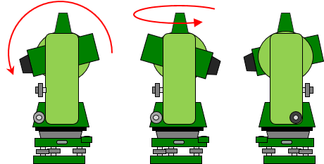 |
| Figure A-5 Direct to Reverse Position |
Which is the direct and which is the reverse TSI position?
On TSIs with a display on a single side of the instrument, it is convenient to call the direct position the one in which the display faces the operator; the reverse position would be with the display opposite the operator.
On dual display TSIs generally the direct position is when the vertical circle is to the operator's left side. This is also referred to as circle left or face left. The reverse position would have the vertical circle to the operator's right (circle right or face right), Figure A-6.
 |
 |
|
| (a) Direct: Left | (b) Reverse: Right | |
| Figure A-6 Vertical Circle Side |
||
Ultimately it really doesn't matter which position is direct or reverse. What's important, as we'll see in TSI applications, is that by measuring in direct and reversed positions many instrumental errors are compensated.
5. Summary
The Global Positioning System (GPS) is fast becoming the preferred tool of most surveyors, but the TSI is still the best instrument in many situations. It is relatively inexpensive, durable, and flexible, able to perform many functions other instruments cannot.
In any measurement science, appropriate instruments and proper procedures are critical for efficient accuracy. Any tool correctly used is very effective, using the wrong tool or the right tool the wrong way will yield poor results. TSI measurement procedures incorporate reversion principles where possible to minimize instrumental errors. The reasons why may not always be apparent in procedure descriptions. For a better understanding the reader should read through Topic XV Chapter G. Theodolite and Total Station. Links to this chapter will be included in procedure explanations where applicable.