{KomentoDisable}
F. Trigonometric Leveling
1. Principles
Trigonometric leveling is so named because it uses a total station instrument's (TSI) slope distance and zenith angle measurements to mathematically compute an elevation difference which, with a few more bits of information, can be used to determine a point's elevation. Using appropriate procedures, and controlling errors, elevation accuraciy can be better than 0.1 ft. Because trigonometric leveling is not limited to a horizontal line of sight, it is more flexible and provides faster elevation data collection than differential leveling.
a. Elevation determination
TSI slope reduction is discussed in the Electronic Distance Measurement topic. Slope reduction geometry is shown in Figure F-1 and accompanying Equations F-1 and F-2.
 |
| Figure F-1 Trigonometric Relationships |
 |
Equation F-1 | |||
 |
Equation F-2 | |||
| H: Horizontal distance Z: Zenith angle S: slope distance |
V: Vertical distance R: Earth radius k: Refraction constant |
|||
The terms in brackets in both equations account for earth curvature and atmospheric refraction. These are systematic errors which are compensated mathematically. The refraction constant is generally taken as a percentage of earth curvature. At low to medium altitudes k = 0.14 (14%), at higher altitudes k=0.07 due to a thinner atmosphere. Earth radius, R, is 20.906x106 ft
For short distances, earth curvature and refraction drop out and the equations become simplified. Most TSI have the option to turn on the corrections.
Vertical distance, V, is the elevation difference between the TSI and the reflector. Adding V to the TSI elevation gives us the reflector elevation. What we want, however is the elevation of the ground point at the reflector location. To determine that, we need two additional pieces of information: (1) TSI elevation, and, (2) height of the reflector above the ground point. Once we have those, then the elevation of any observed point, i, is computed from:
| Elevi = ElevTSI + Vi - HRi | Equation F-3 | |
|
ElevTSI: Elevation of the TSI |
||
b. Sideshots
Besides the way the elevations are determined, another major difference between trigonometric and differential leveling is point connectivity. In differential leveling we normally have one BS and one FS at each set up - we survey in then out of each elevation point. Trigonometric leveling is used when a number of elevations are measured from a single instrument set up. All those points are surveyed into, but not out of. Each elevation point determined by trigonometric leveling is an open link, also known as a sideshot.
In a closed differential level network, Figure F-2(a), each point has a BS and FS; each is connected to another point and their elevations are based on the BM.
Figure F-2(b) depicts a trigonometric network referenced to the differential network. Points B, C, and D serve as control for trigonometric leveling. The green shots at points B, C, and D are all sideshots. Because sideshots are not connected to other points their elevations cannot be checked. An elevation error could be in an individual sideshot measurement or a control point elevation error which affects all the sideshots from that point
 |
 |
|
| (a) Control Network | (b) Sideshots | |
| Figure F-2 Control Network and Sideshots |
||
2. Determining TSI elevation
a. TSI set up over known elevation
In this scenario the TSI is set up over a point whose elevation is known. The elevation must be transferred to the TSI by measuring the Height of the Instrument, HI, Figure F-3.
 |
| Instrument Height Figure F-3 |
The TSI's elevation is calculated from:
| ElevTSI = Elev + HI | Equation F-4 | |
| Elev: Point reference elevation | ||
The HI is the vertical distance from the reference elevation to the TSI's Horizontal Axis (HA). Because the TSI is over the point, it is not possible to directly measure the HI. Most TSIs have an HA index mark on one or both standards which can be used to get a close value for the HI. There are two simple ways to measure the HI:
(1) Using a tape or pocket-rod
A cloth tape or pocket-rod can be used to measure the distance from the elevation reference to the HA index mark, Figure F-4.
 |
| Figure F-4 Measuring HI with Tape |
(2) Using a prism pole
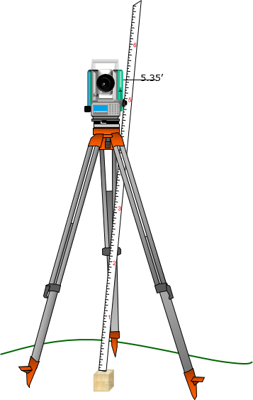
Another method is to place the prism pole next to the instrument and raise or lower the reflector so its center lines up with the HA index mark, Figure F-5. The reflector pole reading is recorded as the HI.
 |
| Figure F-5 Measuring HI with Prism Pole |
Each method is subject to errors which will be discussed in a following section.
b. Sight to known elevation
The TSI is set up at a location from which a reference elevation or benchmark (BM) is visible. The vertical distance is measured to a reflector held on the BM, Figure F-6.
 |
| Figure F-6 Using Benchmark to Establish TSI Elevation |
The elevation of the TSI is determined from:
| ElevTSI = ElevBM + HRBM-VBM | Equation F-5 |
3. Error Sources and Behavior
a. Instrumental
Instrumental errors affecting total station distance and vertical angle measurements also affect trigonometric leveling results. These are described in the Total Station Instruments topic.
This section describes instrumental errors centering on the reflector rod.
(1) Reflector height (HR)
(a) Principle and behavior
If the reflector pole is set to 5.70 ft, is it really 5.70 ft from the bottom of the pole to the center of the reflector, Figure F-6?
 |
| Figure F-6 Prism Pole Uncertainty |
There are a few reasons the reflector pole reading may be incorrect:
How the reflector is mountedMost screw onto the top of the pole and are held in place using a lock nut. Depending on how far down the reflector is screwed will affect its height above the ground, Figure F-7. This is a systematic error.
|
 |
|
| Figure F-7 Reflector Mounting Height Difference |
||
Type of reflector usedDifferent reflector designs, single versus multiple reflectors, Figure F-8, have different center locations. This is also a systematic error.
|
 |
|
| Figure F-8 Reflector Type Height Difference |
||
Pole tipA regular pointed tip can sink in soft ground changing the reflector height. A topo shoe, having a blunt tip, is often used instead of the pointed tip. The blunt tip prevents the pole sinking in the ground maintaining a consistent HR regardless the terrain. But... The height of the topo shoe may be different than the pointed tip which could affect the pole height reading accuracy, Figure F-9. A pointed tip sinking is a random error; height difference between a pointed tip and topo shoe is a systematic error.
|
 |
|
| Figure F-9 Pole Bottom Height Difference |
||
(b) Compensation
Use a topo shoe; unless surveying primarily on hard surface
(b) If a tape or pocket-rod is used to measure HI...
... it should also be used to set the HR.
For example, assume the HI measured with a tape is 5.35 ft, Figure F-10(a). With the reflector set to the same height using the tape, the pole reading is 5.52 ft, Figure F-10(b). Had the HR been set using a 5.35 ft pole reading, there would be almost 0.2 ft error in each measured elevation. The difference between the HI and the reading on the pole is a systematic error.
 |
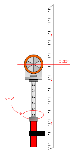 |
| (a) Taped Height | (b) Prism Height |
| Figure F-10 Prism Height Systematic Error |
|
(c) If the reflector pole is used to measure the HI...
... then as long as the same pole is used to measure points any height error is compensated. That's because the error is added in the HI and subtracted in the HR to determine point elevations.
However, an HI error can be introduced if the if the ground isn't flat, Figure F-11, making the pole bottom higher or lower than the point.
 |
| Figure F-11 Uneven Ground Slope |
In those situations a tape should be used to determine the HI and to set the reflector height.
If sighting a reference BM to establish the TSI elevation, Figure F-6, then pole reading error is automatically compensated as long as the same pole is used throughout. The pole height error is added to obtain the TSI elevation, then subtracted for point elevations. However, the TSI elevation will be incorrect by the pole reading error in the HRBM.
(2) Pole bubble
The reflector pole not being truly vertical has a greater effect on horizontal distance than vertical distance measurement. That's not to say a maladjusted bubble should be used for trigonometric leveling because that operation is generally combined with horizontal angles and distances to perform three dimensional surveys. The bubble on the reflector pole should be checked and adjusted as described in the XV. Equipment Checks and Adjustments B. The Grunt Stuff.
b. Natural
The same environmental conditions affecting distance measurement and angle measurement also affect trigonometric leveling.
c. Personal
Most personal errors are same as those in setting up a TSI and measuring angles with it:
- instrument setup (random)
- recording (mistake)
- computations (mistake)
- sighting (random)
along with HI and HR determination (both are mistakes).
How much HI error is introduced because the vertical distance from the ground to the TSI center can't be directly measured?
Example: For a typical set up, the taped distance is 5.25 ft from the ground to the TSI HA index mark. Using a 0.6 ft wide TSI, the true HI can be computed from simple trigonometry, Figure F-12:
 |
| Figure F-12 HI Measurement Error |
In this case, an error of only 0.02 ft is introduced in the TSI elevation. That's not much although it's not up to differential leveling standards. This is one reason we usually limit trigonometric leveling results to 0.1 feet.
Care and experience can eliminate mistakes and minimize random errors.
4. Summary
Trigonometric leveling is a fast efficient way to measure many elevations from a single set up. Being based on a TSI, the process is more flexible than differential leveling.
Whereas in differential leveling the primary instrument is relatively simple, trigonometric leveling depends on a TSI which integrates more measurement types and hence more errors to control. In trigonometric leveling, the surveyor has the option to trade accuracy for productivity depending on the project at hand. Trigonometric leveling does not replace differential leveling but augments it. Differential leveling can be used to build a vertical control network for a project; trigonometric leveling can use that control to collect additional elevation data for design or quantities determination.
Combining trigonometric leveling with horizontal coordinate geometry allows the surveyor to work, design, and implement, in three-dimensions.