{KomentoDisable}
E. Projection Selection
A grid coordinate system is developed based on the needs of its users. It there are a spectrum of applications, the system must support the highest accuracy needs. Design criteria can be divided into two general categories: Coverage area and Projection parameters.
1. Coverage Area
a. Projection Type(s)
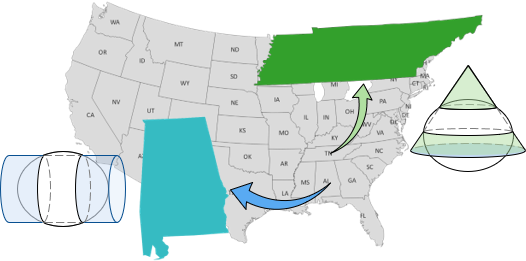
The shape of the area will determine if a cylindric or conic projection fits best. Consider designing statewide systems, Figure E-1:
- A conic projection would be appropriate for Tennessee because it is long east to west
- A cylindric projection would be for Alabama because it is long north to south
 |
| Figure E-1 Selecting Appropriate Projections |
A squarish state (geographically, not mentally), like Wyoming, could use either.
b. Maximum Distortion
The larger the area covered, the greater the distortions. Although distortions are systematic, a maximum is generally specified that is within acceptable limits for most users. This in turn will affect the amount of area that can be covered by a projection or even the type of projection used.
For example, a single cylindric projection for Alabama might not meet a specific maximum distance distortion. If the state is divided into north and south zones, a conic projection could be used for for each, Figure E-2.
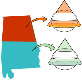 |
| Figure E-2 Using Two Projections |
Most regional coordinate systems are designed to meet a maximum distortion level. In the original State Plane Coordinate (SPC) systems, the limit was 1/10,000. As a result, most state SPC systems used multiple over-lapping zones since a single zone, like the Alabama example, allowed too much distortion.
c. Projection Placement
(1) Zone Extent
Secant projections are preferred for creating regional coordinate systems because they allow scale to range from less than 1 to greater than 1. This balances the overall scaling effect.
Zone extent (ZE) is the maximum distance a zone extends in the direction of varying scale; north-south for a Lambert Conic, east-west for a Transverse Mercator Cylindric. The projection is fit so two-thirds of the ZE is between the scale = 1 lines, the remaining third is split into two equal distances outside. Figures E-3 and E-4 show how a conic and transverse cylindric projections are fit.
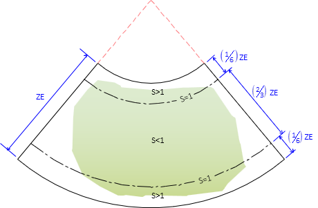 |
| Figure E-3 Conic Projection Fit |
A transverse cylindric projection is fit similarly, Figure E-4, to achieve an averaging scale effect.
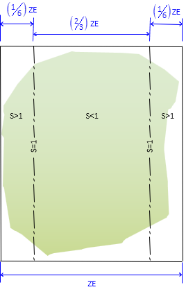 |
| Figure E-4 Transverse Cylindric Projection Fit |
(2) Central Meridian
The Central Meridian (CM) defines Grid North for the coordinate system and its longitude locates the projection east-west.
2. Projection Parameters
Projection parameters define and locate the grid coordinate axes to the projection.
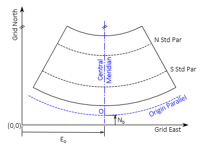
a. Lambert Conformal Conic, Figure E-5
 |
| Figure E-5 Lambert Conic Projection Parameters |
Along with the CM longitude, parameters for a conic projection define:
Latitudes of the North and South Standard Parallels (where scale = 1)
Latitude of the Grid Origin, O
False Northing and Easting which fix the axes origin, (0,0), to the Grid Origin.
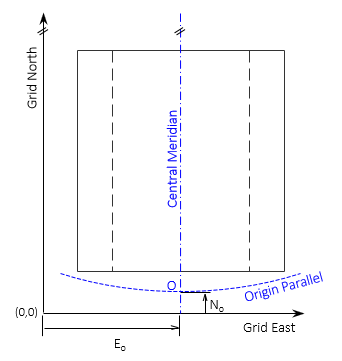
b. Transverse Mercator Conformal Cylindric, Figure E-6
 |
| Figure E-6 Transverse Mercator Cylindric Projection Parameters |
Along with the CM longitude, parameters for a cylindric projection define:
Scale along the CM
Latitude and longitude of the Grid Origin, O
False Northing and Easting which fix the axes origin, (0,0), to the Grid Origin.
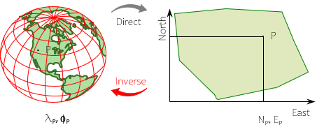
3. Coordinate Conversion
Because of the math connection between the ellipsoid and grid, coordinates on one can be converted to coordinates on the other, Figure E-7.
 |
| Figure E-7 Coordinate Conversion |
Coordinate conversions are:
- Direct (or Forward) - geodetic to grid
- Inverse - grid to geodetic
Using the projection equations and parameters, measurable conversion errors will not be introduced.
4. Almost there...
We have most of the pieces, we just have to start putting things together.