C. Datum
1. Fitting an Ellipsoid
Because measurements are referenced to the geoid, an ellipsoid is selected and fit to it. The geoid is irregular so no single ellipsoid fits it perfectly. Fitting an ellipsoid requires some degree of compromise.
a. Regional Fit
One approach is to fit an ellipsoid to a specific region of the geoid. Figure C-1.
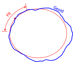 |
| Figure C-1 Regional Ellipsoid Fit |
A centrally located point is used as the fit origin where the ellipsoid and geoid coincide. Parameters that are fixed:
- The point's geodetic latitude and longitude (see Section 3)
- Azimuth of a line from the origin point
- Two ellipsoid parameters
Either the minor axis is set parallel to the Earth's axis of rotation or the deflection of the vertical is specified. The deflection of the vertical, δ, is the angle between the vertical line and ellipsoid normal., Figure C-2. The ellipsoid normal lies in the meridian. Because the vertical line is defined by gravity, it is normal to the geoid so is not restricted to the meridian. δ can have two components- one in the meridian and the other perpendicular to it.
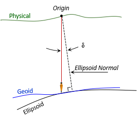 |
| Figure C-2 Deflection of the Vertical |
Making the geoid and ellipsoid coincide assumes the two surfaces do not separate significantly throughout the area. This was a reasonable assumption for an early datum definition before a good mathematical geoid model was available. The error introduced wasn't significant for most surveys.
Different regions would use their own ellipsoid sizes and fits to meet their needs, Figure C-3.
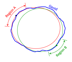 |
| Figure C-3 Multiple Fits |
Of course, what fit one area wouldn't fit well anywhere else. That was of little consequence before global measurements were possible.
b. Global fit
Evolution of global measurement systems required developing models that weren't limited to regions. A geocentric ellipsoid, Figure C-4, is used.
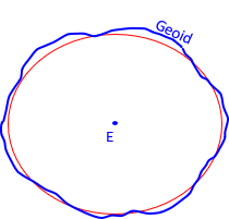 |
| Figure C-4 Geocentric Fit |
Fitting parmeters are
- Location of the coordinate system origin (see Section 3)
- Orientation of the major and minor ellipsoid axes
- Two geometric ellipsoid attributes
2. Heights
Unless the ellipsoid is made to coincide with the geoid, separations between the surfaces vary, Figure C-5.
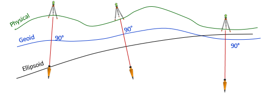 |
| Figure C-5 Geocentric Earth Model |
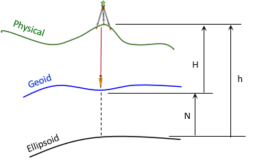
There are three heights at each point, Figure C-6:
- H: Orthometric height; from the geoid to the ground point; elevation determined by leveling from a benchmark
- N: Geoid height; from the ellipsoid to the geoid. Also known as the geoidal height.
- h: Geodetic height; from the ellipsoid to the ground point. Also known as the ellipsoidal height.
 |
| Figure C-6 Heights |
The heights are related by Equation C-1.
| Equation C-1 |
3. Coordinate System
Part of datum definition is creation of a coordinate system for the entire mathematical model. Its origin is set at, or very close to, the Earth's mass center.
a. Geodetic Coordinates
Geodetic coordinates are similar to geographic coordinates, except they are based on an ellipsoid instead of a sphere.
The sphere on which geographic coordinates are based, Figure C-7, has a constant radius throughout.
 |
| Figure C-7 Geographic Coordinates |
The line from the observer's position is radial to the sphere center and normal to the sphere's surface, Figure C-8.
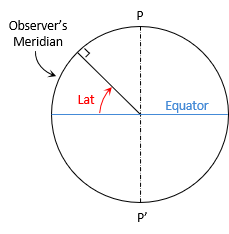 |
| Figure C-8 Geographic Latitude |
The geographic latitude is the angle in the observer's meridian from the equator to the radial line.
With an ellipsoid, the line normal to its surface at the observer's position does not extend to the ellipsoid center, Figure C-9, except at the poles and equator.
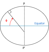 |
| Figure C-9 Geodetic Latitude |
The normal terminates on the minor axis. The geodetic latitude, φ, is the angle from the major axis to the normal line.
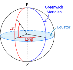
The geodetic longitude, λ, is the angle in the equatorial plane between the Greenwich and observer's meridians.
Geodetic latitude and longitude are shown in Figure C-10.
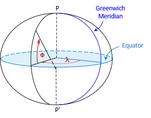 |
| Figure C-10 Geodetic Coordinates |
A point's 3D position is given by its geodetic coordinates and ellipsoidal height.
b. Linear Coordinates
Geodetic coordinate have similar disadvantages as geographic coordinates. An alternative is the Terrestrial Reference System (TRS), a 3D orthogonal linear coordinate system, Figure C-11.
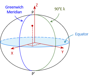 |
| Figure C-11 Terrestrial Reference System |
Like geodetic coordinate system, it is a geocentric system. The X and Y axes are in the equatorial plane with X passing through the Greenwich Meridian and Y through 90°E longitude. The Z axis is perpendicular to the equatorial plane and positive through the North Pole.
A point's 3D position is given by its (X,Y,Z) coordinates.
Although TRS is a linear system, it is not convenient for surveying or mapping applications because of coordinate magnitudes. For example, the coordinates of a control point in southcentral Wisconsin is 21,919.631m X, -4,679,204.603m Y, 4,320,134.562m Z. Their size makes them cumbersome to work with.
4. Datum Realization
The final step is to adjust the control network measurements. Once the adjustment is completed, the datum is created and ready for use.