{KomentoDisable}
F. Parallax
1. StereoPhoto Geometry
The basic geometry of an overlapping photo pair is shown in Figure F-1. Each point in the overlap area appears on both photographs. They appear in different locations on both photos; this is what allows us to see the image in 3D.
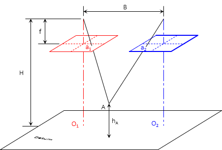 |
| Figure F-1 StereoPhoto Geometry |
Except for stricly photo interpretation, we would also like to use the geometry to determing a point's numeric lcation. To do that, we need to undertand and use parallax.
2. Definition
Remember parallax? When using a telescoped instrument, parallax occurs when the sighted object and crosshairs don't come to exact foucs on the back of the observer's eye, Figure F-2. Moving the head slightly will cause one image to move across the other.
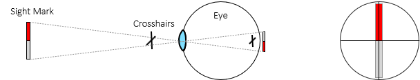 |
| (a) Initial sight |
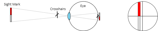 |
| (b) Eye slightly shifted sideways |
| Figure F-2 Parallax |
We don't want parallax when using a telescope because it causes sighting error BUT in stereophotography, parallax helps us determine point distances. Parallax is the amount a point moves between two photos.
Figure F-3 shows two points at different elevations appearing on two successive photos.
 |
| Figure F-3 Successive Photos |
The parallax for each point can be compared by overlaying the photos, Figure F-4.
 |
| Figure F-4 Parallax Distances |
From Figures F-3 and F-4 it is apparent that parallax is:
- a measurable quantity
- related to elevation: the higher the point, the larger its parallax.
Since parallax can be measured, elevations can be determined provided sufficient support information is available.
3. Measuring Parallax
There are two ways to measure parallax depending on object type and accuracy: monoscopic and stereoscopic.
a. Monoscopic
Parallax direction is parallel with the flight direction. Since the photo x axis is in the direction of flight, parallax can be computed from x coordinates, Figure F-5 and Equation F-1.
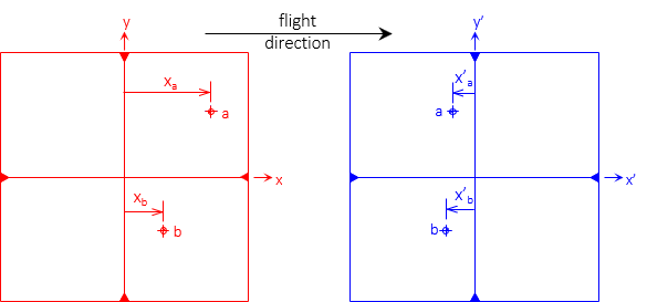 |
| Figure F-5 Parallax Direction |
The coordinate system should be based on the flight path since the images shift in that direction (see Chapter D Section 4 of this topic). However unless there is severe course change between photos, using the fiducial system on both photos should be sufficient for most surveying applications.
To visualize parallax distances, Figure F-6 shows the left and right images of points a and b on a single diagram.
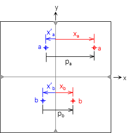 |
| Figure F-6 Parallax determination |
 |
Equation F-1 |
In order to use the monoscopic method, the image point(s) must be distinct on both photographs. Is is extremely difficult, if not impossible, to determine parallax for points in open fields, on water, etc. For those and similar situations, the stereoscopic method must be used.
b. Stereoscopic
In the stereoscopic method parallax is measured in the 3D view using a floating mark. A floating mark is an artificial object added to both photos so it appears in the 3D view. As the two marks are moved closer together or further apart, it will appear to float higher or lower in the model.
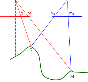
Figure F-7 shows two floating marks on a stereogram.
|
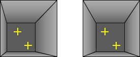
In the 3D view, they appear at different elevations because of their different parallaxes.
The floating marks are etched on glass plates attached to a measurement scale which allows their spacing to be changed. The device is called a parallax bar, Figure F-8.
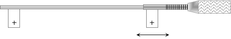 |
| Figure F-8 Parallax Bar |
The glass plates are placed on the images, Figure F-9, and their spacing adjusted until the floating mark "sits" on the object in the 3D model. That places the individual marks at correct parallax distance for the elevation.
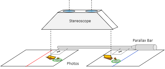 |
| Figure F-9 Using a Parallax Bar |
The parallax distance is determined using Equation F-2.
| Equation F-2 | |
|
C: Parallax bar constant |
|
The constant is determined by using Equation F-1 to determine the parallax of a point, then measuring it with the parallax bar, Equation F-3.
| Equation F-3 |
The advantage of a parallax bar it it can be used on indistinct as well as distinct points. You can float the point until it sits on the ground. then read the scale to determine its parallax.
4. Parallax Equations
a. Ground Coordinates
The ground coordinate system is similar to that of a single vertical photo. The origin and axes directions are defined by the left photo, Figure F-10, using the actual flight direction.
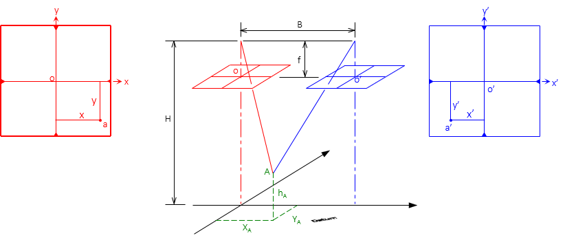 |
| Figure F-10 Ground Coordinate System |
Coordinates and elevation of ground points can be determined from parallax measurements using equations F-4 through F-6.
 |
Equation F-4 |
 |
Equation F-5 |
 |
Equation F-6 |
b. Elevations by Parallax
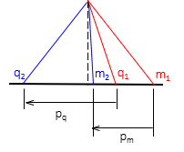
Figure F-11 shows the basic parallax and elevation geometry for two points.
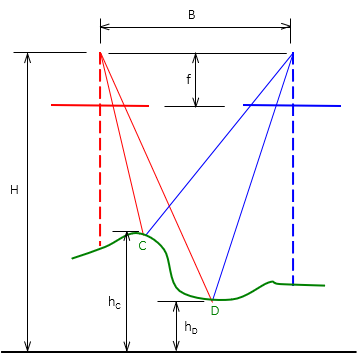 |
| Figure F-11 Parallax and Elevation Difference |
If we can measure the parallax of both points, we can determine one point's elevation based on the other, Equation F-7.
 |
Equation F-7 |
5. Examples
Example 1
Two vertical control points appear on adjacent aerial photographs. Photography flying height is unknown although it is needed for later computations. The elevation and and x coordinate on each photo for the points are:
| Point | Elev (ft) | x (mm) | x' (mm) |
| T34 | 882.53 | 60.922 | -35.909 |
| M60 | 849.93 | 29.538 | -66.379 |
Determine the flying height.
Solution
Compute parallax for both points

Re-arrange Equation E-8 to solve flying height

H = 4.30x103 ft
Example 2
A telecommunication tower appears on overlapping photographs. Coordinates of its top and bottom are:
| Left | Right | |||
| Point | x, mm | y, mm | x, mm | y, mm |
| Bottom | 23.84 | -15.61 | -12.41 | -15.62 |
| Top | 29.75 | -47.85 | -18.23 | 47.89 |
The terrain is generally flat and elevation at the tower base 1125 ft. The flying height was 3550 ft and camera focal length 152.44 mm. What is the tower height?
Solution
Compute parallax for tower top and bottom
![]()
Use Equation E-7 but don't add the tower's base elevation.

Elev = 590 ft