{KomentoDisable}
E. Taping
1. Theory
A tape is a thin ribbon of metal with uniform markings used to measure distances. It replaced a chain which consisted of links and rings, a portion of which is shown in Figure E-1.
|
|
| Figure E-1 Chain Portion |

A chain was a flexible measuring device, however the links and rings would eventually wear requiring length adjustment at the handles. It was also heavier and links were subject to bending if not carefully handled. A tape doesn't have physical connections and is relatively light. It has uniform thickness along its length which makes major instrumental errors systematic easier to compensate procedurally or mathematically.
2. Application
In a nod to tradition, the taping process is often called chaining. The tape itself is sometimes referred to as a chain, the lead person the head chainperson, the following the rear chainperson.
a. Tape types
There are two types of tapes: cut and add. Both are marked and label at one foot intervals with only a single foot near the beginning divided into 1/10's and 1/100's (some have the last foot subdivided also). When measuring a distance, the zero end of the tape leads. This allows direct partial tape readings with minimal mental math.
A cut tape has the first foot, from 0 to 1, subdivided. It is 100 feet long, Figure E-2.
|
|
| Figure E-2 Cut Tape |

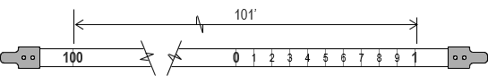
An add tape has an additional foot past 0 that is divided. It is 101 feet long, Figure E-3.
|
|
| Figure E-3 Add Tape |
An cut tape is so called because the partial foot reading at the forward mark is cut (subtracted) from the full foot held at the back mark, Figure E-4.
|
63' - 0.76' = 62.24' |
|
Figure E-4 |

With an add tape, the partial foot reading at the forward mark added to the full foot held at the back mark, Figure E-5.
|
62' +0.24' = 62.24' |
| Figure E-5 Reading an Add Tape |

b. Typical equipment
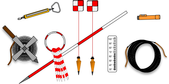
A taping crew would generally be equipped with a tape (on a reel or thrown), chaining pins (aka, arrows), plumb bobs, range poles, hand level, and tension handle, Figure E-6.
|
|
| Figure E-6 Taping Equipment |
For precise base line measurement, a taping buck (a small tripod) would be used instead of chaining pins for intermediate marking. The the tape would be made of invar, a material with lower thermal expansion than steel, and stored on a larger reel to minimize curling.
c. Taping
Taping as a primary accurate distance measuring method has largely been replaced by electronic and satellite-based methods. Because of that, this section presents only a general overview of the process. Most surveying text books describe the procedure in much more detail if the reader is interested.
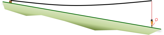
If the terrain between points is flat and obstruction-free, the tape can be laid on the ground, Figure E-7(a). If the terrain slopes or is irregular, the tape must be suspended at one or both ends to measure horizontally, Figure E-7(b).
|
|
| (a) Fully Supported |
|
|
| (b) End Support |
| Figure E-7 Terrain Effect |

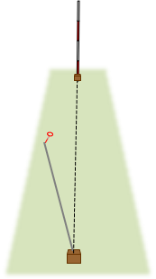
The hand level helps determine how high to hold the tape for horizontal measurement and the plumb bob to orient over a point; it is used by the downhill chainperson, Figure E-8.
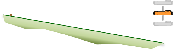 |
| Figure E-8 Using a Hand Level |
The range pole is placed behind the forward point and the rear chainperson uses it to visually keep the forward chainsperson on line.
Sufficient pull must be applied to properly stretch the tape as well as minimize sag when the tape is suspended at its end(s). These are more fully explained in the Errors section.
3. Errors
a. Calibration
A tape is a simple device, but measurements with it are subject to a number of errors. Unlike many other survey measurements, taping errors cannot be compensated with reversion. Systematic taping errors can be eliminated by procedure or computations. Many of these require the tape be calibrated and that differences between calibration and measurement conditions be compared. Tape Calibration is covered in the XV. Equipment Checks and Adjustments topic.
b. Instrumental
(1) Tape length
(a) Principle and Behavior
A tape is 100.00 feet long under specific physical conditions. Calibration may indicate a tape is 100.00 ft long at a particular pull which may not be easy to achieve in the field. For example, calibratiion may determine that 27.2 pounds is needed to stretch the tape to 100.000 ft. At a more comfortable 20 pound pull if may be only 99.970 feet long. If we apply 20 pounds in the field, that means every time we measure 100.00 ft with the tape, we're actually measuring 99.970 ft. That amounts to 0.030 ft of error per full tape length. We would subtract the error from the observed measurement since our measurement would be long.
Because the material and cross-sectional area of a tape is constant, the error is uniform along the length of the tape. The error behavior is systematic.
(b) Compensation:
Procedural: Apply the pull indicated by calibration results to stretch the tape to 100.00 ft.
Mathematical: Apply a specific pull during measurement. Use the differnce between calibration and use pulls to determine the correction. Equation E-1 is the error as a ratio (ft/ft, m/m, etc) and Equation E-2 is the total correction for a measured distance.
|
|
Equation E-1 |

EL: Error
LC: Calibrated length
LN: Nominal length (eg, 100.00 ft)
 |
Equation E-2 |
CL: Total length correction
LM: Measured distance
(1) Sag
(a) Principle and Behavior
The weight of a tape will cause it to sag when it isn't supported along its length and pull the ends together.The sag approximates a parabolic curve which causes the error to be nonlinear. The error for a 100 ft tape segment is more than the total error of two consecutive 50 ft segments, Figure E-9.
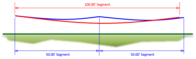 |
| Figure E-9 Sag Behavior |
Sag is a function of the tape weight and the pull applied to it.
(b) Compensation
Procedural: Sufficient pull cannot be applied in the field to completely remove sag nor the error it causes for an entire tape length. However, it can be substantially reduced by using shorter unsupported sections. This can be be accomplished by using a support at mid-tape.
Mathematical: Equation E-3 is the error for an unsupported length of tape.
|
|
Equation E-3 |

w: weight of tape per unit length = total weight / length
LU: Unsupported length; cannot exceed length of tape
P: pull applied during use
The error is always negative since sag cannot be eliminated.
To determine the total correction in an measured distance, the error for each different unsupported length must be computed and added together, Equation E-4.
 |
Equation E-4 |
CS: Total sag correction
ESi: Error for each unsupported segment
For example, a distance was measured with three full 100 foot segments and one partial 56.23 foot segment, all supported ends-only, using 20 pounds of pull. The tape weighed 0.021 pounds/foot.
The error for LU=100 ft is -0.046 ft, for LU=56.23 ft it is -0.008 ft.
The total correction for the 356.23 ft measurement is 3(-0.046 ft)+1(-0.008 ft) = -0.146 ft.
A common mistake is using the entire 356.23 ft distance in Equation E-3. That's saying a single 356.23 ft long tape section was supported only at its ends and would giving an error of -2.077 ft.
Notice in the example that the error for a 100 ft segment is much greater than twice the error of the 56.23 ft segment. As mentioned in the Procedural compensation, by introducing a support midway along the tape, sag error is reduced considerably, from -0.146 ft to -0.016 ft.
c. Natural
(1) Temperature
(a) Principle and Behavior
Changing the temperature of an object will change its size. How much it changes depends on the temperature differential and the material's thermal expansion coefficient. The latter defines size change as a ratio per degree of temperature. Alloys can be blended to make some objects more dimensionally stable. Because a tape has consistent uniform composition along its entire length, it expands or contracts uniformly. That means for the same temperature increase, a 50 ft segment of a tape expands half the amount as a 100 segment of the same tape.
(b) Compensation
Procedural: It's not feasible to replicate calibration temperature in the field. Instead, a mathematical correction should be applied.
Mathematical: Equation E-5 is the temperature error as a ratio.
 |
Equation E-5 |
ET: Error as a ratio (eg, ft/ft, m/m)
T: Temperature during use
TC: Temperature during calibration
k: Thermal expansion coefficient, ft/ft/°F (Metric: m/m/°C)
Equation E-6 is the temperature correction for a measured distance.
 |
Equation E-6 |
CT: Total temperature correction
LM: Measured distance
(2) Wind
(a) Principle
Wind effects a plumb bob when trying to line up over a point. It also causes an elevated tape to flutter, making it difficult to hold the tape steady and apply a consistent pull.
(b) Behavior
Taken all together, wind has a random effect on taped measurements.
(c) Compensation
Procedural: Avoid windy days. If elevating the tape, use shorter unsupported segments. This reduces the amount of tape exposed to the wind and keeps plumb bob line lengths shorter on sloped terrain.
Mathematical: There is no mathematical wind compensation for wind as its effect is random.
d. Personal
(1) Pull
(a) Principle and Behavior
A tape must be stretched out to its full 100.00 foot length; how much pull needed is determined by calibration. The amount may be too high for comfortable application in the field so a different one may be used. If under-pulling, the tape will be shorter than its marks indicate causing measurements to be too high, over-pulling has the opposite effect.
Because the tape has a uniform cross-section and homogeneous material structure through-out, the error behavior is systematic and linear: the error in a 50 foot segment is half the error in a 100 ft segment.
(b) Compensation
Procedural: Consistently apply the calibration derived pull for a 100.00 ft length.
Mathematical: A tape's stretching resistance under tension is a function the its cross-sectional area and material's Modulus of Elasticity. Equation E-7 is the pull error as a ratio, Equation E-8 the correction for a measured distance.
 |
Equation E-7 |
EP: Error as a ratio
P: Pulled applied for measurement
PC: Calibration pull
A: Cross-sectional tape area
E: Modulus of elasticity
 |
Equation E-8 |
CP: Total pull correction
LM: Measured distance
(2) Alignment
(a) Principle and Behavior:
The shortest distance between two points is a straight line. Any measurement longer than a single tape length is subject to misalignment, Figure E-10, introducing an error.
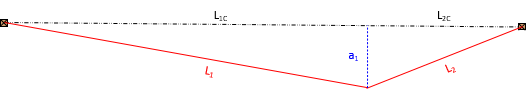 |
| Figure E-10 Misalignment. Plan View |
The error behaves systematically.
(b) Compensation:
Procedural: It's the rear chainperson's responsibility to ensure the tape is aligned. Placing the range pole behind the point measured to helps the rear chainperson keep head chainperson on line, Figure E-11.
 |
| Figure E-11 Rear Chainperson View |
Mathematical: Because straight lines are involved, the misaligned distance, L1, can be corrected, L1C, if the tape's off line distance, a1, is known. Then it becomes a simple Pythagorean equation solution, Equation E-10.
 |
Equation E-10 |
(3) Horizontal
(a) Principle and Behavior
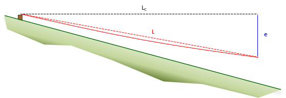
Distances between points are horizontal. Holding one end of the tape above or below horizontal along sloping terrain will introduce an error, Figure E-12.
 |
|
Figure E-12 |
A sloped distance is longer than its horizontal equivalent. The error is systematic.
(b) Compensation
Procedural: The lower chainperson should use a hand level to determine how high the tape must be held to be horizontal.
Mathematical: Slope distance, L, can be corrected to horizontal, LC, if the distance the tape is above or below horizontal is known, e. The correction, Equation E-11, is similar to tape misalignment.
 |
Equation E-11 |
(4) Marking/Plumbing
(a) Principle and Behavior
Intermediate points must be marked with a chaining pin. This is relatively easy with the tape on the ground; it becomes more difficult with the tape elevated and a plumb bob used while applying sufficient pull to stretch the tape and minimize sag. Taping uphill means the rear chainperson must try to center the plumb bob over a mark while also applying appropriate pull. All together these have a random effect on tape measurements.
(b) Compensation:
Procedural: On sloped ground, keep tape segments short to allow the tape to be held lower. Using plumb bob is easier because it's closer to the mark and swing is easier to control. Holding the tape too high can be an unstable situation. Waist-high or lwere is best.
To hold the plumb bob on the tape, wrap its string around the foot mark a few times, Figure E-13(a), then hold in place with the thumb, Figure E-13(b), when gripping the tape.
 |
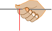 |
| (a) Wrap | (b) Holding |
| Figure E-13 Plumb Bob Line |
|
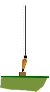
Make sure the plumb bob does not come into contact with the ground or mark. Doing so can cause the plumb bob to tip creating an offset vertical line, Figure E-14.
 |
|
Figure E-14 |
If the plumb bob swings, lightly tap in on the ground or mark to stop it.
To set a chaining pin, hold the plumb bob a foot or so above the ground. When ready, drop the plumb bob allowing it to penetrate the gound. Carefylly remove it and insert the chaining pin in the hole. Insert the pin perpendicular to the line and 45° to the ground.
When taping along a slope requiring frequent short sections, use the breaking chain method, Figure E-15,
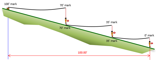 |
| Figure E-15 Breaking Chain |
The rear chainperson holds the 100' tape mark on the first point. The forward chainperson selects a convenient foot mark to hold and uses that to set a pin. He/she drops the tape and the rear chainperson holds the same mark on the pin for the next segment measurement. The forward chain person moves to the next convenient foot mark and repeats the process. When the 0 ft mark pin is set, the total distance measured is 100 feet. No calculations are needed.
Taping uphill is the same basic process except the rear chainperson determines how high to hold the tape which affects which whole foot mark the head chainperson can use.
Mathematical: Because these errors behave randomly, mathematical compensation ins not possible. Careful procedures muse be used instead.
(5) Reading; Recording
(a) Principle and Behavior
Common errors include
- Incorrectly reading cut and add tapes
- Miscounting full tape segments
- Recording measurements incorrectly
- Forgetting to record use conditions
These errors are all mistakes.
(b) Compensation
Procedural: Familiarization with tape type - review reading with crew mate(s). Because each full tape length is marked with a chaining pin, the rear chain person should collect the pins as the line is measured. Unless breaking chain, the number of pins is the number of full tape lengths. Measure the line in both directions. Exercise care recording measurements; use a standard field notes format to ensure all data is faithfully recorded.
Mathematical: Because these are mistakes, they cannot be compensated mathematically. Careful measurements with attention to procedures are the only way to eliminate these mistakes.
4. Example Taping Corrections
a. Information
A steel add tape was calibrated at 70°F with full support and found to be 100.004 feet long under 23 pounds of pull. Its weight and cross-sectional area were measured and recorded as 2.2 pounds and 0.004 sq in. The tape steel had a modulus of elasticity of 2.9x10⁷ psi and thermal expansion coefficient of 6.5x10⁻⁶ ft/ft/°F.
The tape was used on a day when the temperature was 50°F. A distance was measured and recorded as 436.48 ft. The first two full tape segments were fully supported. The remainder of the line consisted of end only support segments: two 100 ft and one 36.48 ft, Figure E-16.
 |
| Figure E-16 Example 1 |
A tension handle was used to apply a consistent 15 pound pull for all measurements.
b. What is...
the correct measured distance for the use conditions?
(1) Incorrect tape length
Set up and solve Equations E-1 and -2

(2) Temperature
Set up and solve Equations E-5 and -6

(3) Pull
Set up and solve Equations E-7 and -8

(4) Sag
Determine the tape's weight per foot. The entire tape weighed 2.2 pounds. Because it's an add tape, it is 101 ft long. Also, at both ends of the tape is an additional half-foot.

Use Equation E-3 to determine the sag error for a full tape length

Use Equation E-3 to determine the sag error for a full the last partial length

Use Equation E-4 to compute the total sag corrections

(5) Corrected length
Add the corrections to the measured distance.
