{KomentoDisable}
G. Theodolite and Total Station
1. Instruments
Transits, theodolites, and total stations are an evolutionary family. Although newer instrument types replaced older, their uses often overlapped as adoption took place. Because their measurement functions are fundamentally the same, they are subject to similar instrumental errors and compensation methods. The more sophisticated later instruments have fewer user-accessible adjustments by design and use electronics to digitally compensate some maladjustments.
a. Transit
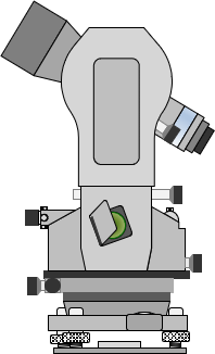
A traditional transit, Figure G-1, is an open design instrument with four leveling screws. Its adjusting screws are easily accessible and most of its moving parts, including the angle reading system, are exposed. This open exposure leads to faster wear and more frequent maladjsutment.
| Figure G-1 Transit |
Transits are obsolete, used primarily for shelf display so they are not covered in this chapter. Most of their checks and adjustments parallel a theodolite's but if demands warrant, I can create a separate chapter for transits.
b. Theodolite
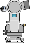
A theodolite, Figure G-2, is an enclosed design with an optical reading system and three leveling screws. Most adjusting screws are are under covers or otherwise protected and its moving parts are better sealed than a transit's. When carefully used, a theodolite is less susceptible to maladjustment than a transit.
 |
| Figure G-2 Theodolite |
Theodolites were produced for a broad spectrum of needs, from construction to high accuracy control surveys, resulting in models with different capabilities and controls. Some had a separate bubble for manual vertical circle orientation, others an automatic gravity-actuated circle. A repeating theodolite used an upper and lower horizontal circle lock and slow-motion, a directional theodolite only a single lock/slow-motion assembly. Early theodolites were analog instruments with an optical angle reading system; later instruments were digital.
Except for vertical circle orientation, primary theodolite checks and adjustments are similar across different models. Those unique to a particular instrument are explained in the instrument's manual.
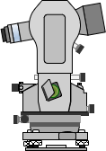
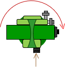
c. Total Station
A total station instrument (TSI), Figure G-3, shares mechanical characteristics, including enclosed design and three leveling screws, with a theodolite. A TSI uses a digital angle reading systems and incorporates an electronic distance measurement (EDM) capability. Most TSIs also have the ability to self-correct some instrument maladjustment conditions.
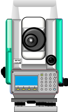 |
| Figure G-3 Total Station |
Many theodolite maladjustment are the same for TSIs. Digital and electronic systems, particularly those with no TSI equivalent, require specific checks. These are detailed in an instrument's manual. Because they have similar parts and controls, theodolite and TSI checks are combined; those specific to one or the other are called out.
A modern TSI compensation system measures axes tilts and corrects angle measurements accordingly. A particular TSI may use a single axis system which corrects only zenith/vertical angles for axis tilt or a dual-axis system which also corrects horizontal angles errors caused by axes tilt.
That's not to say a TSI's compensation system is infallible. As with any other adjustment aspect of the TSI, the compensation system shouldn't presumed to be without error. While an automatic level's compensator is relatively easy and quick to check, those of a TSI are more complex. The instrument's manual will have information on its compensation system, its sensitivity, and how to check that it is working correctly. Not all TSIs use the same compensation design, even from the same manufacturer, so procedures in the manual should be followed.
2. Instrument Axes
a. Definitions
Instrument axes are illustrated in Figure G-4.
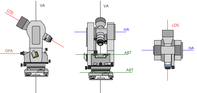 |
| Figure G-4 Instrument Axes |
The axes are also described in I. Basic Principles Chapter E. Bubbles, Axes, and Optics, Oh My!
(1) Line of Sight (LOS).
The LOS is a line through the crosshairs' intersection and objective lens optical center. It is the line along which the operator makes a sight through the telescope.
(2) Vertical Axis (VA)
The VA is the axis about which the instrument rotates in a horizontal plane.
(3) Horizontal Axis (HA)
The HA is the axis about which the telescope rotates in a vertical plane.
(4) Axis of the Bubble Tube (ABT).
An instrument has two different types of bubbles: tube and circular.
The surface of a bubble tube is curved in the direction of its length. Its ABT is an imaginary line tangent to the center of the curved surface, Figure G-5.
 |
| Figure G-5 Tube Bubble |
A circular bubble's surface is a spherical section. Its ABT is a plane tangent to the curved surface's center, Figure G-6. From any side view, the plane appears, and behaves, as a line.
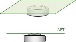 |
| Figure G-6 Circular Bubble |
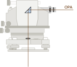
(5) Optical Plummet Axis (OPA).
The OPA is the line of sight through the optical plummet. It consists of two perpendicular segments: the observer's horizontal sight line is bent 90° through an internal prism to a vertical sight line, Figure G-7.
 |
| Figure G-7 Optical Plummet Axis |
b. Relationships
A bubble is used to orient an instrument to gravity which should make its axes, with notable exception, vertical or horizontal For this to happen, specific geometric relationships must exist between an instrument's axes. These are:
- ABT of the tube and circular bubbles perpendicular to the VA.
- HA perpendicular to the VA
- LOS perpendicular to the HA
- OPA perpendicular to and coincident with the VA
A instrumental error exists when any of these conditions is not met. The Reversion Principle can be used to identify many of the maladjustment errors. Most can be compensated procedurally, all by equipment adjustment which makes them systematic errors.
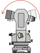
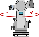
c. Instrument Position
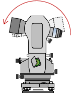
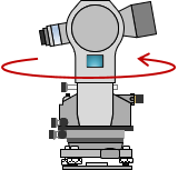
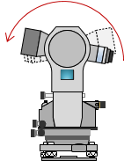
When an instrument is set up, it is either in a direct or reverse position. Position refers to axes orientations. It is changed between D and R by reversing the telescope in vertical plane and rotating the instrument in the horizontal plane, Figure G-8.
 |
 |
 |
 |
| (a) Direct | (b) Reverse Telescope | (c) Rotate Instrument | (d) Reverse |
| Figure G-8 Instrument Positions |
|||
This reverses the axes geometry allowing the Reversion Principle to to compensate an instrumental error either by procedure or adjustment
Another way to refer to position is by the vertical circle's placement with respect to the telescope when viewed from behind. These are called Circle or Face Left and Circle or Face Right. To keep it simple, we will use the direct/reverse designation.
Which position is direct and which is reverse? It really doesn't matter as long as the instrument geometry is reversed between the two.
3. Field Conditions
- Select an open area that allows flat horizontal sights up to several hundred feet in opposite directions to minimize pointing errors.
- A distinct vertical sighting mark at least 30° above the horizon will be needed. A vertical wall works well, although heat waves could be an issue on a sunny day.
- Make sure support hardware is in good operating condition.
- Clear parallax in the main telescope and the optical plummet scope.
4. Checks and Compensations
a. Plate Tube Bubble
(1) Description
The plate bubble is used to accurately level the instrument. The ABT should be perpendicular to the VA. If not, when the bubble is centered the VA will not be vertical.
(2) Check
Roughly level the instrument using the circular bubble.
Rotate the instrument so the ABT is parallel with two instrument leveling screws.
Center the bubble using the two screws.
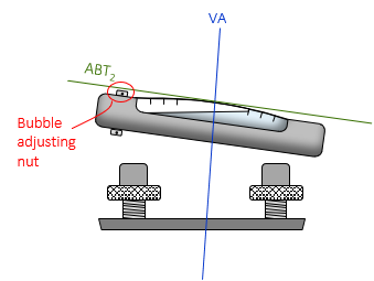
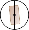
If the ABT is not perpendicular then the VA won't be vertical, Figure G-9.
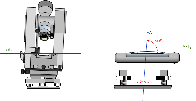 |
| Figure G-9 First Position |
If present, the amount of error is the angle a.
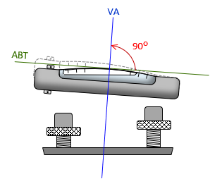
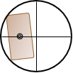
Rotate the instrument 180°. The angle between the ABT and VA is maintained, Figure G-10.
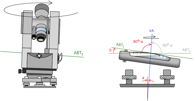 |
| Figure G-10 Rotated Position |
If there is no error, the bubble will stay centered, otherwise it will run to the higher end of the tube. In Figure G-9, the rotated instrument geometry makes angle b twice angle a; the bubble runs twice the error amount.
Generally, if the bubble runs half a division or less, it can be treated as an adjusted condition.
Note
Most TSIs are able to automatically compensate if the instrument is slightly out of level. Some will refuse to measure or display an error if the leveling is too far out. Check your instrument's Operation Manual.
(3) Compensation
(a) Procedure
Using the leveling screws, bring the bubble back half the amount it ran, Figure G-11.
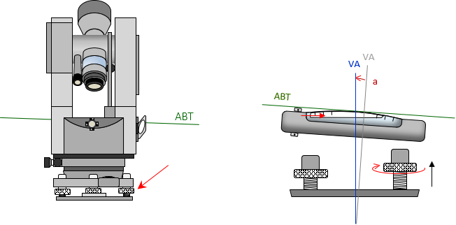 |
| Figure G-11 Procedural Compensation |
This will make the VA vertical. The ABT will be inclined by the error angle, a, so the same of the tube will always be high as the instrument is rotated about the VA.
(b) Adjustment
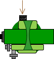
Use the adjusting nut(s) at one end of the tube, Figure G-12, to bring the bubble back half the run, Figure G-13.
 |
| Figure G-12 Adjusting Nuts |
 |
| Figure G-13 Adjusted Bubble |
This will make the ABT perpendicular to the VA. Now when the bubble is centered with the leveling screws, the ABT will be horizontal and VA vertical.
b. Circular Bubble
(1) Description
The circular bubble is used to roughly level the instrument. On most instruments, the circular bubble is tribrach-mounted and does not rotate with the instrument so the Reversion Principle cannot be applied.
(2) Check
Level the instrument using the plate bubble and check the circular bubble. If it is centered, no adjustment is needed.
(3) Compensation
(a) Procedural
Use the plate bubble to level the instrument.
(b) Adjustment
Because the instrument was leveled with the plate bubble the amount the circular bubble is off is the actual amount of maladjustment error.
Use the circular bubble adjusting screws to center the bubble. The screws may be located around the top or bottom of the bubble.
c. Optical Plummet
(1) Description
The optical plummet takes the place of a plumb bob for instrument set up over a ground point. When the instrument is level, the OPA is both horizontal and vertical. The vertical component should coincident with the instrument's VA.
There are two ways to check and compensate for a maladjusted optical plummet depending whether it rotates with the instrument or not. This chapter covers rotating plummets because those are common on theodolites and TSIs. The other type is discussed in Chapter B. The Basic Stuff.
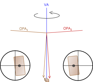
(2) Check
Precisely level the instrument and use the optical plummet to accurately set up over a ground point, Figure G-14.
 |
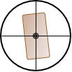 |
| (a) Top View | (b) View Through Plummet |
| Figure G-14 Centered on Ground Point |
|
Rotate the instrument 180° and check the ground point through the plummet, Figure G-15(a).
 |
 |
 |
| (a) Rotate 180° | (b) On ground point | (c) Off ground point |
| Figure G-15 Instrument Rotated |
||
If it is still on the ground point, Figure G-15(b), it is correctly adjusted.
If the plummet it is pulled off the ground point, Figure G-15(c), then it is maladjusted.
The only part of the OPA which can be adjusted is the crosshair reticule in front of the observer's eye. A maladjusted plummet means the crosshairs are either too high or too low so the horizontal segment of the OPA is not horizontal. Because the OPA is bent 90° thru a prism, the vertical segment of the OPA is not vertical, Figure G-16.
 |
| Figure G-16 OPA Maladjustment |
So how much error is there? When the instrument was reversed, the amount the mark moved off the point is twice the error, Figure G-17.
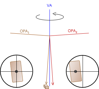 |
| Figure G-17 Maladjusted Optical Plummet |
The instrument is vertically over a point halfway between the ground point and the current plummet sight location, Figure G-18.
 |
| Figure G-18 Instrument Location |
(3) Compensation
(a) Procedural
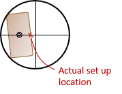
i. By Setup
Carefully loosen the instrument attaching screw.
While sighting through the plummet, slide the instrument across the tripod head halfway back to the ground point.
Tighten the instrument attaching screw.
Rotating the instrument to various positions and checking the plummet shows it follows a circular path centered on the ground point, Figure G-19.
 |
| (a) Set up |
| (b) Plummet Path |
| Figure G-19 Procedural Compensation |
ii. By Plumb Bob
Use a plumb bob to center the instrument over the ground point. A plumb bob will hang vertically regardless optical plummet condition.
(b) Adjustment
The adjusting screws for the optical plummet crosshairs are located forward of the eyepiece. There may be one to four screws, Figure G-20, and they may be exposed or under a cover.
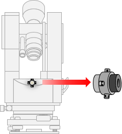 |
| Figure G-20 Adjusting Screws |
To correct the OPA with the adjusting screws:
- If not using a plumb bob, then bring the crosshairs back half the amount of their reversed instrument position. Recenter the instrument and check.
- If using a plumb bob, center the instrument with the plumb bob, then bring the crosshairs to the ground point. Reverse the instrument and check.
d. Line of Sight
(1) Description
The LOS should be perpendicular to the HA to allow straight lines to be prolonged by rotating the telescope in a vertical plane.
(2) Check
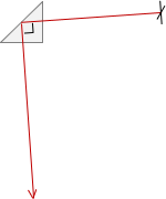
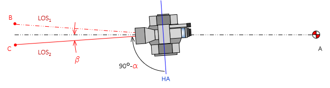
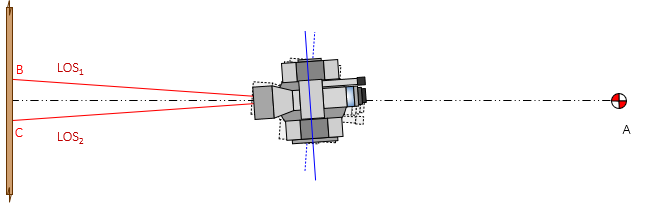
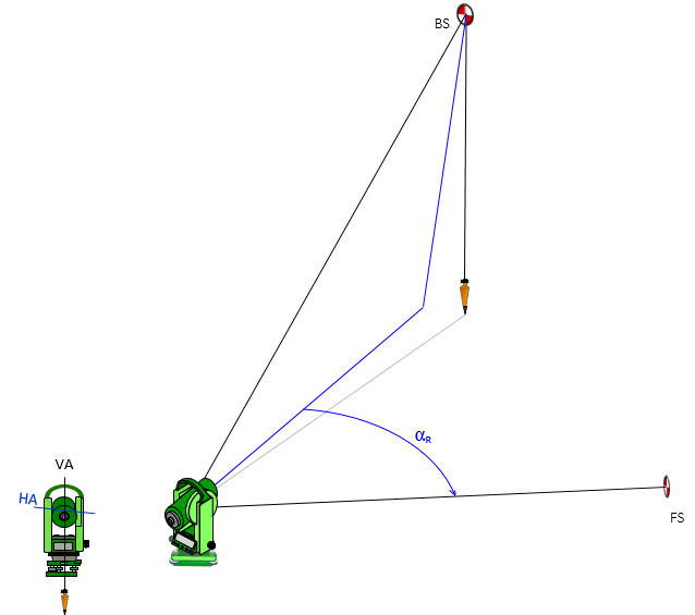
The check is performed by Double Centering. To minimize pointing errors, use sights at least 200 feet long. The instrument is set up and leveled, then a sight is taken on a distinct target or point, Figure G-21.
 |
| Figure G-21 Step 1 |
Angle α is error in the LOS-HA perpendicular condition.
The telescope is rotated about the HA, Figure G-22(a), to set point, B, opposite the instrument from point A, Figure G-22(b).
 |
| (a) Reverse Telescope |
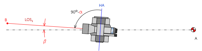 |
| (b) Set Foresight Point |
| Figure G-22 Step 2 |
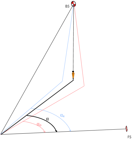
If in adjustment, the instrument and points A and B will be colinear. Otherwise the angle β is twice the error, angle α.
The instrument is rotated around the VA, Figure G-23(a), and point A is sighted again, Figure G-23(b).
 |
| (a) Rotate Instrument |
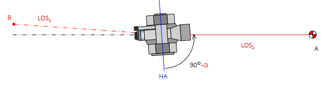 |
| (b) Backsight |
| Figure G-23 Step 3 |
The telescope is rotated about the HA, Figure G-24(a), to set another point C opposite the instrument from point A, Figure G-24(b).
 |
| (a) Reverse Telescope |
 |
| (b) Set Foresight Point |
| Figure G-24 Step 4 |
If in adjustment, points B and C will coincide.
If the LOS is not perpendicular to the HA, the plane in which a vertical angle is measured is offset from the instrument's VA. The further away the point, the greater the offset. Think of the LOS as tracing out a cone as the telescope is rotated, Figure G-25.
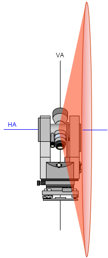 |
| Figure G-25 Maladjustment Effect |
The cone is centered on the instrument and its axis coincides with the instrument's HA.
(3) Compensation
(a) Procedure
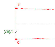
Set the correct colinear point, D, halfway between points B and C, Figure G-26.
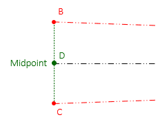 |
| Figure G-26 Procedural Compensation |
(b) Adjustment
Because the instrument was reversed twice, the distance between points C and D is four times the error. To correct the condition, use the crosshair adjusting screws. They are located immediately forward of the eyepiece, usually under a protective cover. Use the horizontal screw(s) to move the crosshairs 1/4 the distance from point C in the direction of point B, Figure G-27.
 |
| Figure G-27 Adjustment |
Note
A level rod laid on its side approximately perpendicular to the line, Figure G-28, can be used if the instrument will be adjusted.
Figure G-28
Using a Level Rod
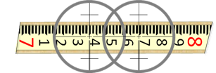
Instead of setting points B and C, readings are taken on the rod, Figure G-29.
Figure G-29
Rod SightsSight distances to points B and C can be shorter since the level rod will be read. This is both easier and more accurate than trying to mark two points. The distance CB can be quickly computed and the adjustment made.
e. Horizontal Axis
(1) Description
The LOS is constrained to rotate around the HA. If the HA is not horizontal when the instrument is level, the LOS will not travel in a vertical plane. This will affect vertical and horizontal angle measurements.
(2) Check
A distinct sight mark at least 30° above horizontal is needed. A wall works well because two additional marks will be set.
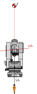
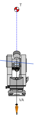
Set up the instrument in the D position, Figure G-30(a).
The HA will be inclined if it is not perpendicular to the VA.
Sight the mark, T. Rotate the telescope to approximately horizontal and set a mark, A, Figure G-30(b).
 |
 |
| (a) HA Orientation | (b) Set point A |
| Figure G-30 HA Check Direct Position |
|
If the HA is maladjusted, the LOS will not follow a vertical path from T to A.
Reverse the instrument to the R position. This will incline the HA in the opposite direction, Figure G-31(a).
Sight the mark, T. Rotate the telescope to approximately horizontal and set a mark, B, Figure G-31(b)
 |
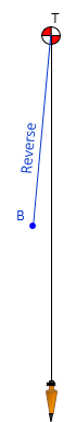 |
| (A) HA Orientation | (b) Set point B |
| Figure G-31 HA Check Reverse Position |
|
As in the D position, if the HA is maladjusted, the LOS will not follow a vertical path from T to B.
If the instrument is in adjustment, points A and B will coincide. Point C vertically below point T is halfway between points A and B, Figure G-32.
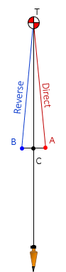 |
| Figure G-32 Vertical Point |
(3) Compensation
(a) Procedure
Modern TSIs have dual-axis compensation to account for horizontal and vertical tilts. Refer to the instrument's Operation Manual for the compensation range and how to check.
Although they provide a degree of self-correction, procedural compensations should still be used with TSIs.
i. Vertical Angle Measurement
The maladjustment cannot be compensated by procedure for a theodolite. In both D and R positions, the vertical angle is inclined so its magnitude is always too large.
To set a point vertically below another, use the check method and set the point as shown in Figure G-32.
ii. Horizontal Angle Measurement
If the bascksight (BS) and foresight (FS) points are at the same vertical angle, the maladjustment will not introduce an error. However, if one point is higher or lower than the other, an error may occur if the LOS must be vertically rotated.
To measure a horizontal angle,
Measure the angle in the D position, Figure G-33.
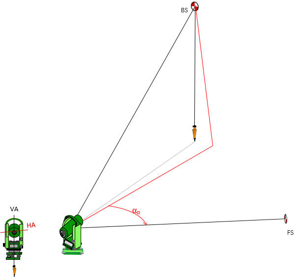 |
| Figure G-33 Horizontal Angle Direct |
Measure the angle in the R position, Figure G-34.
 |
| Figure G-34 Horizontal Angle Reverse |
The correct angle is the average of the D and R angles, Figure G-35.
 |
| Figure G-35 Corrected Horizontal Angle |
(b) Adjustment
Although it is possible to adjust the HA on a theodolite, it is discouraged because it requires opening the instrument and may make the condition worse. If the instrument does require HA adjustment, it should be performed by a qualified repair center.
Do not attempt to adjust a TSI. If the axes compensation checks described in the Operation Manuals fail then the instrument must be sent to a repair facility.
f. Vertical Circle Index
(1) Description
Reducing slope distance to horizontal requires measurement of a vertical or zenith angle. An index error exists if the vertical circle is not correctly oriented to gravity when the instrument is leveled. TSIs and most theodolites use a gravity actuated vertical circle which should orient itself automatically. Some earlier theodolites, particularly control quality instruments, had a separate bubble for vertical circle orientation. Those instruments types aren't addressed in this chapter.
(2) Check
Analog theodolites measure zenith angles; digital theodolites and TSIs can be set up to measure zenith or vertical (from the horizon) angles. We'll use zenith angles*****
Measure the Direct and Reverse zenith angles to a point and check their sum.
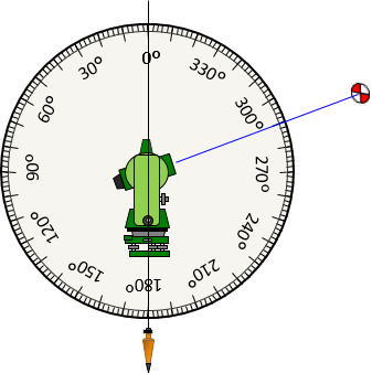
In Figure G-36 the Direct zenith angle is 70°.
 |
| Figure G-36 Direct Zenith Angle |
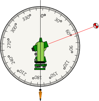
In Figure G-37 the Reverse zenith angle is 290°.
 |
| Figure G-37 Reverse Zenith Angle |
Adding them: 290°+70°=360°
The sum of the Direct and Reverse angles should be 360°
What happens if the vertical circle is rotated 4°, for example?
The Direct zenith angle to the same point, Figure G-38, is 66°, 4° too small.
 |
| Figure G-38 Direct Zenith Angle with Error |
The Reverse zenith angle, Figure G-39, is 286°, also 4° too small.
 |
| Figure G-39 Reverse Zenith Angle with Error |
66°+286°=352°, which is 8° less than 360° and twice the circle rotation. Per Reversion Principle, the error is doubled.
(3) Compensation
(a) Procedure/Mathematical
Because a zenith angle is a continuous angle, the correct angle is not the direct and reverse average. Instead, an Index error is computed and applied to the measured zenith angle.
The Vertical Circle Index error is (360°-[ZD+ZR])/2. It is added to the direct (ZD) and/or reverse (ZR) angle.
For this example, the Index error is (360°-352°)/2 = +4°.
66°+4°=70° check
286°+4°=290° check
70°+290° = 360° check
(b) Adjustment
Neither a theodolite nor a TSI can be mechanically adjusted. Although a theodolite has a physical circle, it is not user accessible. A TSI uses a digital circle which can have 0° anywhere and axes compensation which should account for an index error. An error with either should be only be adjusted by a qualified repair facility