{KomentoDisable}
F. Automatic Level
An automatic level is a relatively simple instrument whose primary function is to maintain a horizontal line of sight. However, "automatic" doesn't mean it's not subject to maladjustment. It has few parts and, except for collimation, its checks are simple and fast.
1. Compensator Check
a. Description
The compensator maintains a horizontal line of sight when the instrument is slightly out of level. A sticking compensator will not react correctly if the instrument's level condition is disturbed.
Checking the compensator is quick and should be done each day the instrument is used.
b. Check
|
(1) Set up and level the instrument. (2) Clear parallax. |
 |
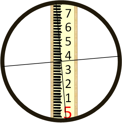
| (3) Sight a level rod and note the reading. |  |
| (4) While sighting the rod, use a finger to firmly and gently press down on the forward end of the telescope. This will deflect the line of sight changing the reading. |  |
| (5) While holding the telescope depressed, the crosshairs should return to the initial reading. This is the compensator reacting as it should. |  |
| (6) Remove pressure from the telescope front; the line of sight will go up and then... |  |
|
(7) ... should return to the inital rod reading. |
|
| Figure F-1 Compensator Check |
|
Another way to check the compensator is to take a reading with the circular bubble centered, turn one of the leveling screws making the instrument slightly out of level, and check the reading again. If the second reading matches the first then the compensator is operating correctly. This must be done with care as turning a level screw too much can change the instrument’s elevation which can affect the second rod reading.
c. Behavior
A level with a sticky or inoperable compensator cannot be reliably used. Its behavior is random and is not apparent when reading a rod.
d. Compensation
If the compensator does not respond correctly, it should be sent in for repair. The internal mechanism is delicate and sealed from dust and should only be adjusted by a qualified service technician.
The remainder of the checks in this chapter should only be performed if the compensator is working correctly.
2. Horizontal crosshair
a. Description
On an adjusted level, the horizontal crosshair is truly horizontal when the instrument is correctly set up. This allows accurate rod reading using any part of the crosshair.
b. Check
|
(1) Set up and level the instrument. (2) Clear parallax. |
|
| (3) Sight a rod with one end of the horizontal crosshair and note the rod reading. |  |
|
(4) While sighting through the telescope, use the slow motion to horizontally scan across the rod. If the reading doesn't change. the horizontal crosshair is in adjustment. |
 |
| Figure F-2 Horizontal Crosshair Check |
|
c. Behavior
As long as the their adjusting screws are not loose, the crosshairs will maintain their orientation resulting in systematic behavior.
d. Compensation
(1) Procedure
Use the crosshairs' intersection for all rod readings, Figure F-3.
|
|
| Figure F-3 Use Crosshair Intersection |
(2) Adjustment
The crosshairs are mounted to a reticule held in place by adjusting screws. Depending on the instrument and its age, it will have 1, 2, or 4 adjusting screws. Figure F-4 shows a typical 2 screw system. These are generally located near the eyepiece underneath a cover. To adjust the horizontal crosshair, both screws are slightly loosened, the reticule rotated, and screws re-tightened.
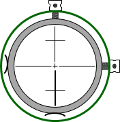 |
| Figure F-4 Reticule |
Unless the horizontal hair is significantly rotated, it's probably best to just always use the crosshair intersection for leveling. Trying to correct a small amout of error could make the situation worse and even introduce collimation error.
3. Collimation
a. Description
On an adjusted instrument which is correctly set up, the LoS should be horizontal and perpendicular to the instrument's VA. A non-horizontal LoS means the instrument has a collimation error. A LoS that is inclined or depressed from horizontal, Figure F-5, introduces a rod reading error.
 |
| Figure F-5 Collimation Error |
Collimation error is caused by the vertical position of the crosshairs: if they are too low then the LoS is inclined; if they are too high, the LoS is depressed.
b. Check
(1) Procedure
Because collimation error cancels if BS and FS distances are balanced, checking for it purposely uses unbalanced sight distances. The elevation difference between two points is determined using a short BS / long FS condition followed by a long BS / short FS condition. If there is a collimation error, the two elevation differences will not be the same.
Because collimation error is a function of distance, the sight length for each reading is needed. The error is then stated as ratio (e.g. ft/ft) or angle above (+) or below (-) horizontal.
A baseline which consists of four roughly evenly spaced points is established. The points should be on an approximately straight line and placed at a uniform interval of 75 to 100 ft, Figure E-6. Points 1 and 2 are instrument locations and are marked with wooden stakes; Points A and B are elevation points and are marked with stable pins.
 |
| Figure F-6 Baseline |
The instrument is set up at point 1 (it does not have to be exactly over the point).
A short BS reading is taken on point A and a long FS reading on point B, Figure F-7
 |
| Figure F-7 First Setup at Point 1 |
The instrument is moved to point 2 (again, it does not have to be exactly over the point).
A long BS reading is taken on point A and a short FS reading on point B, Figure F-8
 |
| Figure F-8 Second Setup at Point 2 |
The elevation difference point A to point B is:
from Point 1: BS1 – FS1
from Point 2: BS2 – FS2
If the two elevation differences are identical, the instrument is in adjustment. If they differ, the instrument has a collimation error.
Including the collimation error, e, in the elevation differences:
from Point 1: (BS1 – e) – (FS1 – 2e)
from Point 2: (BS2 – 2e) – (FS2 – e)
Setting the two differences equal and solving for e:
 |
Equation F-1 |
e is the total vertical error in a horizontal sight distance of d. Collimation error can be expressed as a vertical/horizontal ratio, Equation E-2, or angle, Equation E-3.
 |
Equation F-2 |
 |
Equation F-3 |
Both equations require the average distance, d.
Rather than set the four points accurately at an interval of d, it is easier to set them at the approximate interval and then measure the distances as the readings are made. This is done by Three-Wire Leveling.
The distances from point 1 to A and B and from point 2 to A and B are determined by stadia. The measurements are used to compute an overall average distance, d, Figure F-9, and Equation F-4.
 |
| Figure F-9 Base Line Point Spacing |
 |
Equation F-4 |
|
Besides facilitating distance determination, reading all three horizontal crosshairs provides a check on the rod reading and allows carrying an additional decimal place. Refer to Topic Elevation Determination G. Three-Wire Leveling for a procedure description.
(2) Sample data sheet
Because each BS and FS consists of three rod readings and distances are computed as well as elevation differences, it can be quite easy to get lost in the process. To help, the following data sheet can be used to record readings and perform the collimation computations both as a ratio (c) and vertical angle (θ).
For a full-size pdf version click here; for a spreadsheet template click here.
A collimation check example using this data sheet will be shown shortly.
(3) How much is acceptable?
Table F-1 shows the maximum allowable instrument collimation error for First, Second, and Third Order leveling.
| Table F-1 |
 |
|
From Section 3.5 Geodetic Leveling of Standards and Specifications |
The Standards and Specifications... also state that "Compensator-type instruments should be checked for proper operation at least every 2 weeks of use."
While these are control-level standards, they can serve as a guide for local applications. Local project control might use Third (or possibly Second) Order specifications while that for topographic control would be looser. Regardless, the error in an instrument is not known unless a collimation check is performed.
c. Compensation
(1) Procedure
For most leveling projects, collimation error can be removed by balancing BS and FS distances, that is, making them equal.
 |
| Figure F-10 |
If the BS and FS distances are equal, Figure E-16, then the reading error in both will be the same: eBS=eFS. Because ElevB = ElevA + BS - FS, the BS error (eBS) is added and the FS (eFS) error is subtracted so the collimation error cancels. That means that the elevation of B is correct with respect to A if the BS and FS distances are equal. However, the EI is incorrect since it is subject only to the BS error. That's why in differential leveling we have one BS and one FS per setup and make sure their distances are approximately equal.
(2) Mathematic
Whenever the level is used, the correction could be applied to each reading made, Figure F-11.
 |
| Figure F-11 Unbalance Sight Distances |
The collimation error is compensated by multiplying the correction by the BS and FS length difference and adding it to the elevation difference.
|
|
Equation F-5 |
This requires the length of each sight be captured as the readings are taken. This is the case when Three-Wire Leveling but generally not so when doing basic differential leveling using only the center hair unless paces are counted and recorded.
(3) Adjustment
The reticule adjusting screws are located near the eyepiece under a cover. Removing the cover reveals the adjusting screws at the top and possibly bottom of the reticule (there might also be side adjusting screws but they aren't necessary for this adjustment), Figure F-12.
 |
| Figure F-12 Reticule Adjusting Screws |
If there is an upper and lower screw, then one must be first loosened and the other then tightened to move the crosshairs.
If there is only a single screw then only that screw is loosened or tightened.
How far to move the crosshairs?
For the previous example, we know that the total error in the BS from point 2 to A is: (152 ft)x(-0.0000266 ft/ft) = -0.004 ft.
The correct BS reading should be 5.540+0.004 = 5.544 ft
That means to remove the collimation error, we would use the adjusting screws to raise the crosshairs to a 5.544 ft BS reading.
Hmm... trying to see 0.004 ft at 152 ft... not too easy.
Probably best to leave the crosshairs alone and use one of the other two methods.
d. Collimation Check Example
Instrument used has a stadia multiplier of 100; rod units are feet.
A baseline was laid out with a cloth tape using an interval of approximately 75 feet.
Instrument set up at point 1
Sight rod on A
| Read and record the three crosshairs. |  |
|
Reduced readings: Average should be close to the middle reading, if not, then one or more readings incorrect; re-read. Check: d1A should be approx 75 ft, same as interval. |
 |
It's important to reduce the readings immediately after taking them. The computations help identify if a reading error has been made. If there is an error, the equipment is still in place so the measurements can be quickly redone.
Sight rod on B
| Read and record the three crosshairs. |  |
|
Reduced readings Average should be close to the middle reading, if not, then one or more readings incorrect; re-read. Check: d1B should be approx 150 ft, twice the interval. |
 |
The instrument is moved to Point 2 and the process repeated.
The readings (black) and computations (red) are:
Sight rod on A
Sight rod on B
Compute the error and distance from Equations E-1 and E-4:
A negative error indicates the LoS is below horizontal.
Using Equations E-2 and E-3 express collimation error as a ratio and angle:
-0.0000266 ft/ft is the same as -0.0226 mm/m which means this instrument meets First Order and Second Order standards.