{KomentoDisable}
H. General Optics
1. Introduction
Most surveying equipment, historical and contemporary, depend on various optical elements to make target sighting more accurate or reading measurement scales easier. Surveying equipment evolution closely followed advancements in optical quality improvement. Compare, for example, the telescope of an nineteenth century Dumpy level to that of a contemporary automatic level. The modern telescope is shorter, has greater magnification, provides a brighter image, and has fewer distortions.
This chapter is not the be-all, end-all tome on optics. It discusses some primary optical elements contained in many surveying instruments and their characteristics. Since so many of our measurements depend on optics, a background in basic principles and behaviors helps understand their effect on instrumental errors.
2. Refraction - Snell's Law
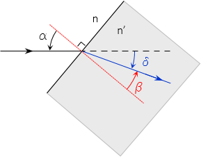
Snell's Law, Equation H-1, describes the amount a light ray deflects when it crosses the boundary between two dissimilar media, Figure H-1.
| Equation H-1 | |
|
n: refraction index of first medium |
|
 |
| Figure H-1 Snell's Law |
Incident and refracted angles are referenced to the surface normal: the line perpendicular to the interface (red line in Figure H-2) at the light ray intersection.
The light ray does not refract if it intersects the interface at a right angle. Figure H-2.
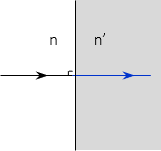 |
| Figure H-2 No Refraction |
Refraction indicies are related to media densities: a denser medium will slow the speed of light. Where density changes, light is bent. Line of Sight refraction was discussed in II. Errors Chapter E. Systematic Errors Sec 3. Curvature and Refraction. The difference is that the LoS passes through an atmosphere of changing density so it is continually bent. Snell's law deals with two different but homogeneous media. Once refracted at the interface, the light ray continues in a straight line until it encounters another interface.
There can be media which do in fact have varying density and bend the light ray internally. These aren't typically used in surveying applications, so we will limit discussion to homogeneous media.
Figure H-3 shows a flat glass plate with air on both sides. A light ray intersecting the panel at an angle is refracted toward the normal in the glass, then away from the normal when it re-enters the air - it only changes direction at the interfaces. The refraction at each interface is the same since there are only two different media.
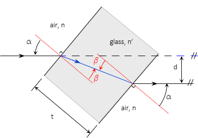 |
| Figure H-3 Flat Glass Plate |
The emergent ray on the right is parallel with the initial ray on the left but displaced. Displacement (d) depends on the initial angle of incidence, plate thickness (t), and refractive indicies, Equation H-2.
 |
Equation H-2 |
Example
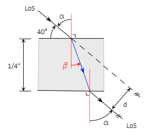
A surveyor's horizontal line of sight passes through a vertical plate glass window. How much is the LoS offset if it intersects the window at an angle of 40° and the glass is 1/4" thick with a 1.50 refractive index? Use 1.00 for the refractive index of air.
Sketch
Because the LoS is horizontal and the window vertical, the offset is horizontal. Looking down from above the displaced LoS looks like this:
Compute the incident angle
![]()
Compute refractive angle

And finally displacement, converted to feet:

3. Reflection
Reflection happens when at least a portion of a light ray is returned from the interface rather than continuing entirely though the second medium. Highly polished surfaces will have some degree of reflection, some are more efficient than others. One of the most efficient is a silver coating on a support medium.
The reflective coating can be on the front or back of the support medium. Figure H-4 shows a flat first-surface mirror with the reflective material on the front.
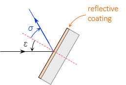 |
| Figure H-4 First-Surface Mirror |
For a flat reflector, the incidence angle, ε, and reflection angle, σ, are equal (think of a bank shot in pool or billiards with no spin on the cue ball). If the light ray intersects the reflector at 90°, Figure H-5, it is reflected back along its original path.
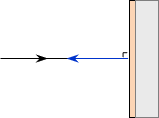 |
| Figure H-5 Reversed Reflection |
First surface mirrors are used where distortion free sight lines are important because light rays are affected only by reflection. A reflective coating on the back of a glass plate means the light ray must pass through the glass first causing it to be refracted. Once reflected, it is refracted again when it emerges from the glass, Figure H-6.
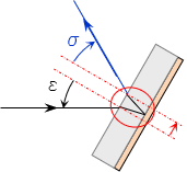 |
| Figure H-6 Back-Surface Mirror |
While the incident and reflection angles are correct, the light ray has been displaced because of the refractions.
Unless specifically designed not to, most reflective coatings will allow some light to pass through. An example is a one-way mirror - on one side of the mirror a person sees only their reflection but their image passes through and is visible to observers on the other side. Their image, however, does not pass back through the mirror.
4. Prisms
A prism is generally a glass block of a specific geometric shape, Figure H-7.
 |
 |
 |
| (a) Right angle | (b) Penta | (c) Dove |
| Figure H-7 Common Prisms |
||
Prisms are used to redirect and/or reorient light rays by refraction and reflection.
For light passing from a dense medium to a less dense one, Figure H-8, there is a critical incidence angle at which the refracted angle is exactly 90°
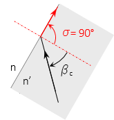 |
| Figure H-8 Perpendicular Refraction |
The light ray does not pass out of the denser medium. The incidence angle at which this occurs is the critical angle and can be computed using Equation H-3.
 |
Equation H-3 |
When the incidence angle exceeds the critical angle, the light ray will be entirely reflected, with no part of it refracting through the interface, Figure H-9.
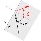 |
| Figure H-9 Internal Reflection |
Prisms use this internal reflection to change the direction of light rays. Some prism applications in surveying that we'll cover later are:
- An optical plummet bends the line of sight 90° using a right angle prism
- A reflector for distance measurement uses three coinicident right angle prisms to reflect an electromagnetic signal back along its path
- An automatic level's compensator uses prisms to maintain a horizontal line of sight
5. Thin Lens
a. Description
A thin lens is a narrow medium that has at least one curved surface for gathering light rays from distant objects. One or both sides of the lens are spherically convex or concave surfaces. Curvature radii and material density affect the lens' refraction and focusing characteristics. Figure H-10 shows just a few possible lens types.
 |
| Figure H-10 Different Thin Lenses |
To the human eye, a distant object may be hard to see while a close one too small to make out detail. Visible objects emit light rays in all directions. A lens collects these rays to create an image that is generally larger than perceived with the naked eye, Figure H-11.
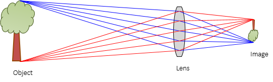 |
| Figure H-11 Lens Use |
b. Focal length
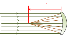
The curved surface(s) together with Snell's Law cause the light rays to converge on one side of the lens. Light rays from an object at infinity (or at least very far away) are parallel and converge to a point at a specific distance from the lens. That distance is the focal length, f, of the lens, Figure H-12.
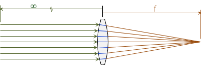 |
| Figure H-12 Parallel Rays and Focal Length |
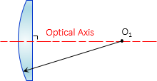
Even if oblique to the lens, Figure H-13, parallel light rays converge at the focal distance, although the focus point shifts parallel with the lens.
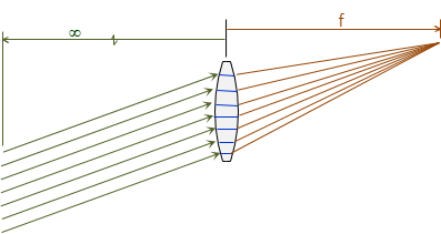 |
| Figure H-13 Oblique Light Rays |
The focal length is computed using Equation H-4.
 |
Equation H-4 |
|
n: refractive index of lens material |
|
Using the convention of light rays traveling from left to right as in Figure H-11, R1 is radius of the left lens surface facing the object, R2 is the right surface.
- R1 is positive if its curvature center is on the image side, negative on the object side.
- R2 is positive if its curvature center is on the object side, negative on the image side.
The radius of a flat side is infinity.
Figure H-14 shows radius sign conventions for a few different lens types.
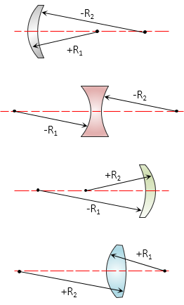 |
| Figure H-14 Radii Sign Convention |
If the focal length is positive, the lens is a convergent lens, a negative focal length makes it a divergent lens. The image formed by a convergent lens is on the side opposite that of the object's, Figure H-15; the image of a divergent lens is on the same side as the object, Figure H-15.
 |
| Figure H-15 Divergent Lens |
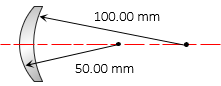
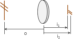
Example:
What is the focal length of the lens shown below? Its refractive index is 1.54.

c. Optical axis
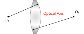
The optical axis is a line connecting the curvature centers of both sides, Figure H-16(a). For a lens with one flat side, it is the line from the curvature center perpendicular to the flat side, Figure H-16(b).
 (a) Two curved surfaces |
 (b) One flat surface |
| Figure H-16 Optical Axis Definition |
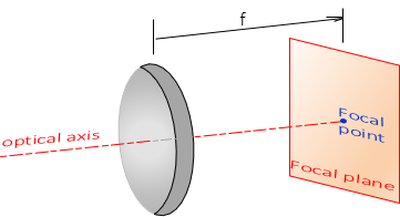
d. Focal point; Focal plane
The focal point located on the optical axis at the focal distance. The focal plane is perpendicular to the optical axis at the focal point. Figure H-17.
 |
| Figure H-17 Focal Point and Plane |
Light rays parallel with or oblique to the optical axis will come to focus at a point somewhere the focal plane.
e. Lens Equation; Image plane
The focal length is the distance at which an object located at infinity will come to focus. When the object distance is much less than infinity, the lens must be moved relative to the focal plane for the image to be sharp. The Lens Equation, Equation H-5, defines object and image distances and focal length relationships.
| Equation H-5 | |
|
f: focal length |
|
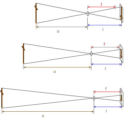
For a given lens, its focal distance is fixed; changing the object distance changes the image distance. As object distance approaches infinity, image distance approaches the focal length., Figure H-18.
 |
| Figure H-18 Object and Image Distance Behavior |
Consider a Single Lens Reflex (SLR) camera, Figure H-19: to focus on an object, the lens barrel is rotated which moves the lens in and out changing the image distance. This is a mechanical solution of the lens equation.
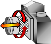 |
| Figure H-19 Focusing a 35mm Camera |
The image plane is similar to the focal plane except it moves as the image distance changes. The image and focal planes coincide for distance objects.
Example
A camera has a 135 mm focal length lens. Determine image distances for 1, 10, 100, and 1000 meter object distances.
Re-arrange Equation H-5 to solve it in terms of image distance. Because object distances are in meters, include a meter to millimeter conversion factor:

At 1 m object distance:

Substituting the remaining object distances:
| Object dist, m | Image dist, mm |
| 1 | 156.1 |
| 10 | 136.8 |
| 100 | 135.2 |
| 1000 | 135.0 |
Notice how the image distances approach the focal length as shown in Figure H-18.
e. Flip it
A single thin lens inverts the image which isn't an issue for many applications. For others, like the view through an instrument's telescope, an upright image is preferred. Adding a second lens will re-invert the image, Figure H-20.
 |
| Figure H-20 Upright Image |
6. Combining Optical Elements
a. Compound Lens
Why all the different types of thin lenses? A small single thin lens is generally not strong enough to magnify distant objects and details. A physically larger and thicker single lens would gather more light for a brighter and more detailed image, Figure H-21.
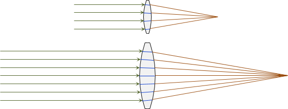 |
| Figure H-21 Small vs Large Lenses |
It is more difficult to create a single large lens with a constant surface geometry and uniform refraction index throughout. Glass blanks are made by cooling molten glass. Uniform cooling of a large molten mass can be difficult, creating internal stresses leading to structural defects and refractive index variation.
A larger lens also requires a larger support structure, ie, a bigger camera, telescope, etc. Where space is a consideration, such as in an airplane, a more compact optical assembly is required.
A compound lens system, Figure H-22, combines different types of thin lenses.
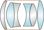 |
| Figure H-22 Compound Lens System |
Thin lens quality is easier to control so the resulting compound lens has fewer distortions than a thick lens. Focusing a large thick lens requires moving the entire lens generally over a long range. With a compound lens system only a few elements are moved and over a relatively short distance.
b. Optical systems
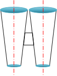
Mirrors, prisms, and lenses can be combined to create compact and powerful optical packages. A simple example is a set of binoculars, Figure H-23. Early binoculars, Figure H-23(a), were just a pair of straight telescopes mounted together with a common focusing system. Maximum size of the objective lenses was limited by the spacing between the telescopes which in turn was limited by user eye spacing. To increase magnification required longer and heavier telescopes.
 |
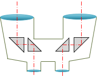 |
| (a) Straight | (b) Prismatic |
| Figure H-23 Binoculars |
|
Most modern binoculars are prismatic type, so-named because they contain prisms to alter the sight paths, Figure H-23(b). A right angle prism redirects a light ray 90°. Using a pair of right angle prisms for each eye's sight line:
- spaces the objective lenses further apart so larger ones can be used. Larger lenses have greater light gathering capability so the image is brighter.
- increases focal lengths while keeping a compact case size. This facilitates higher image magnification.
Another example is the optical system of an SLR camera, Figure H-24.
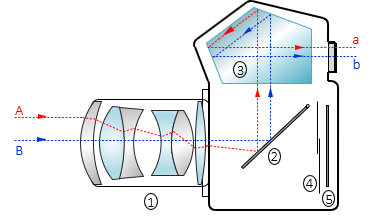 |
| (a) Pre-exposure |
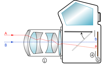 |
| (b) Exposure |
Figure H-24 Single Lens Reflex Camera |
Primary components are: (1) Compound lens, (2) First-surface mirror, (3) Pentaprism, (4) Shutter, (5) Focal plane (film or sensor array).
Light rays from the image are redirected using the mirror (2) and pentaprism (3) to the viewfinder where the camera operator sees the object in an upright position. The image size is reduced but not distorted by the optical paths. To capture the image, the mirror (2) flips up, the shutter (4) opens, and the image is recorded on the focal plane (5).
7. Aberrations and Distortions
a. Aberrations
Aberrations degrade image quality causing blurriness and loss of detail. There are three primary aberrations:
(1) Spherical, Figure H-25. Caused if either lens surface is not a perfect sphere. Light rays striking the lens at different locations will not come to focus at the same image distance.
(2) Astigmatism, Figure H-26. Generally the results when surface curvature in one direction differs from curvature in another. Perpendicular objects focus at different image distances.
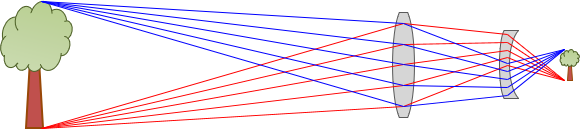
(3) Chromatic, Figure H-27. A light ray is composed of different component colors, each with their own frequency. Each color frequency refracts slightly differently. The blue component refracts most, with a shorter image distance, red the least with the longest image distance. A rainbow is a naturally occurring example of chromatic aberration.
 |
| Figure H-25 Spherical |
 |
| Figure H-26 Astigmatism |
 |
| Figure H-27 Chromatic |
b. Distortions
Distortions affect image geometry. There are two distortions, Figure H-28:
(1) Radial, r's in Figure H-28. Faulty lens geometry alters the emergent light ray displacing it radially from the image center, o.
(2) Tangential, t's in Figure H-28. The optical axes of individual lenses in a compound lens must coincide. A misalignment will cause the emergent light ray to displace perpendicularly to the radial line from the image center, 0.
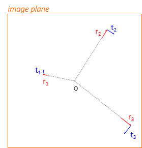 |
| Figure H-28 Distortions |