{KomentoDisable}
C. Measuring Horizontal Angles
1. Before We Start...
a. Angle Sets
Angles are generally measured as direct and reverse (D/R) sets. How many sets are needed and how close the direct and reverse angles must be to each other depends on a number of things: survey purpose, TSI resolution, sight lengths, etc. 2. Incrementing the Circle
b. Advancing the Circle
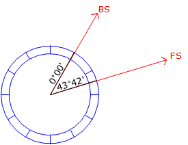
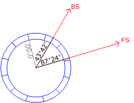
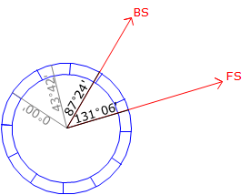
When measuring a horizontal angle with a repeating theodolite or transit, the horizontal circle was advanced so different parts of it would be used for the measurements. This would help compensate for circle irregularities such as axes eccentricity and division spacing irregularities. The most common method was to bring the initial FS angle back to the BS to serve as the beginning of the next measurement, Figure C-1. The angular value accumulated with successive measurements.
|
(a) First measurement |
|
(b) Second measurement |
|
(c) Third measurement |
| Figure C-1 Advancing the Circle |
An upper and lower horizontal lock and slow motion was needed to accomplish this. Each would be used at different points in the measurement to either hold the circle or allow it to rotate.
TSIs generally have only a single lock and slow motion for the horizontal circle. The circle itself is electronically encoded so zero can be anywhere the operator chooses. Because the display is digital, the operation can also freeze or hold the reading so it doesn't change as the TSI is rotated. Manipulation of the lock and holding the reading allows the angle to accumulate also on a TSI. We'll use this method to simulate circle advancement.
2. Measuring a Horizontal Angle
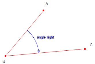 |
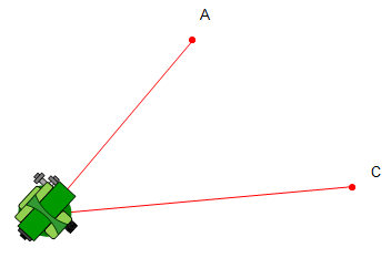
| Figure C-2 Example Angle Measurement |
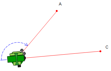
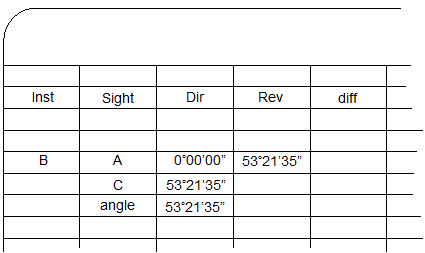
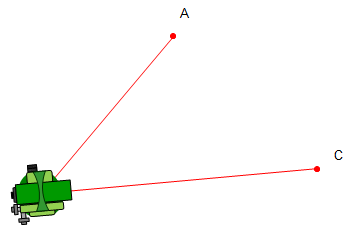
This section will describe an angle measurement procedure and recording the readings. In our example, the TSI will occupy point B and measure the angle right (clockwise) from A to C, Figure C-2.
There are various note formats which can be used depending on the project and other measurements being made. Running a traverse, for example, would use a format which incorporates distances as well as angles.
For this example, we will use a simple angle only format.
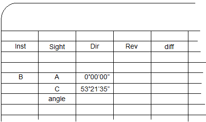
The procedure and notes are shown in Figure C-3.
Click here for a video of this example.
|
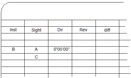
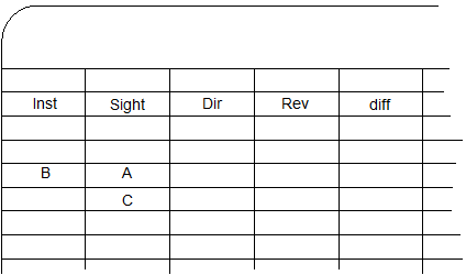
Set up the column headings.
|
 |
|
The TSI is set on point B. |
|
|
|
|
|
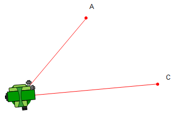
The lock is released and TSI rotated in the direction of the angle to point C. In this case, to the right. |
|
 |
 |
|
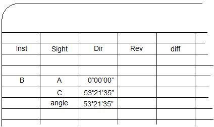
The value of the angle is the difference between the FS and BS readings. Compute and record it immediately after the FS reading is made. This is the direct angle. |
 |
 |
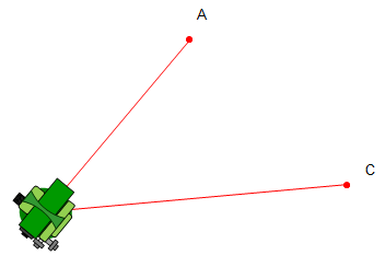
The telescope is reversed about the HA so it points away from C. Then the horizontal lock is loosened and instrument rotated to the right back to point A. |
|
Using the lock and slo-mo, point A is accurately sighted. |
|
 |
 |
|
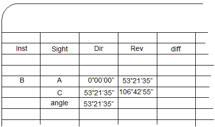
The lock is released and TSI rotated right to point C. |
|
 |
 |
|
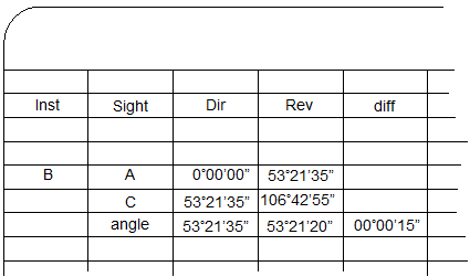
The value of the reverse angle is the difference between the FS and BS readings. The direct and reverse angle should be close. Their difference should be primarily due to instrumental and pointing errors. The difference is recorded in the diff column. |
 |
|
The process would be repeated for the number of D/R sets required. Successive direct and reverse angle sets should be relatively consistent taking into account random errors. |
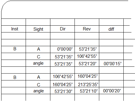 |
| If all the angles are within acceptable limits, the final angle is computed as the average of all the D/R angles. |  |
| Figure C-3 Angle Measurement Process and Notes |
|
3. Notes Clarity
a. Zeroing BS readings
Because it's easy to do on a TSI, it's tempting to zero the horizontal angle reading on each BS sighting, Figure C-4.
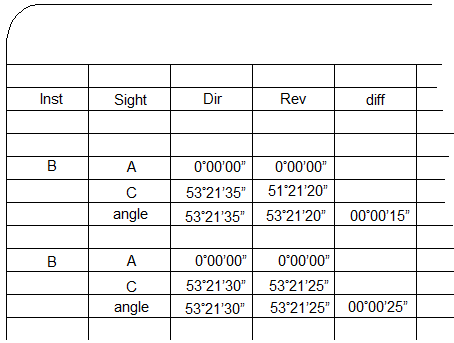 |
| Figure C-4 Resetting Angle |
While easier to calculate the angle, it can be confusing to a third party. How were the measurements made?
As two complete D/R sets, or,
Two direct measurements first rotating back and forth between A and C, then two reverse measurements rotating back and forth between A and C?
Allowing the angle to accumulate without zeroing intermediate BS sightings makes it clear the order in which the measurements are made.
b. Mistake
Inevitably, a mistake is made, either reading the instrument, sighting, or incorrectly locking/unlocking the angle display. This will show in the notes as an angle with an excessive D/R difference. Figure C-5 shows a mistaken reading and how to correctly deal with it.
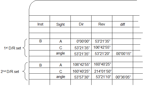 |
The large difference for the second D/R set is an indication of a mistake. Upon closer investigation, it looks like the mistake occurred on the second direct angle as the second reverse angle "fits" with the first D/R set. |
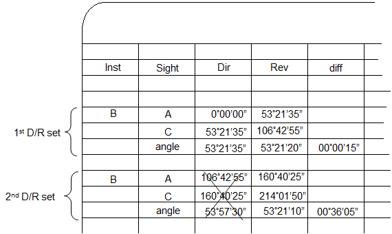 |
The initial inclination is to toss the second direct angle and keep the second reverse angle. |
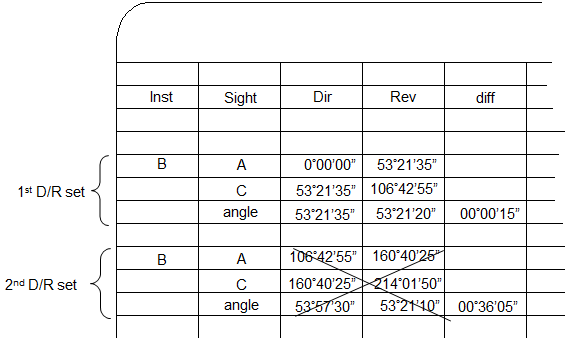 |
However, accepting the reverse angle without a corresponding direct one doesn't compensate instrumental errors. The correct way to address the mistake is to reject the entire second D/R set... |
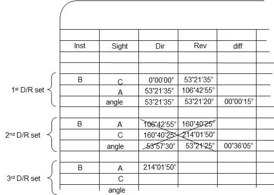 |
.. and measure a third D/R set.
|
| Figure C-5 Correcting An Angle Measurement Error |
|
4. Measuring a Deflection Angle
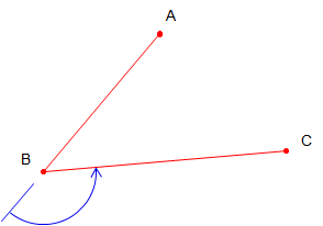
A deflection angle is measured from the extension of the previous line to the next line, Figure C-6. It is either to the right (clockwise) or left (counter-clockwise).
 |
|
Figure C-6 |
The procedure to measure a deflection angle is the same as for an angle right (or left) except for when the instrument is reversed. To measure the deflection angle at point B from Point A to point C, after the TSI is set up at point B:
Step (1) Sight point A with the TSI in the reverse position.
Step (2) Rotate the telescope about the HA until it is pointing away from point A along the extension of line AB.
Step (3) Zero the horizontal angle and record it.
Step (4) Release the horizontal circle lock and rotate to point C in the direction of the angle (left in this case).
Step (5) Using the horizontal lock and slo-mo, sight accurately on point C.
Step (6) Freeze the angle reading and record it.
Step (7) Compute the deflection angle by subtracting the BS reading from the FS reading. This is the direct angle.
Step (8) Release the horizontal circle lock and rotate to point A.
Step (9) Using the horizontal lock and slo-mo, sight accurately on point A.
Repeat steps (2)-(7) to measure the reverse deflection angle.
